
Resin inspection well and manufacturing method thereof

A manufacturing method and resin technology, which is applied in the field of resin manholes and its manufacture, can solve problems such as obstruction of drainage, energy waste, and failure of normal construction, and achieve the effects of saving construction costs and shortening the installation period

Inactive Publication Date: 2012-12-19
巢善鸣 +1
View PDF0 Cites 3 Cited by
  • Summary
  • Abstract
  • Description
  • Claims
  • Application Information

AI Technical Summary

Problems solved by technology

[0002] In the prior art, inspection wells are generally made of red bricks, cement, and mortar, and the whole is a rigid structure. The mortar on the inner wall is easy to fall during use, which not only hinders drainage but also makes sewage seep from the inner wall, or groundwater Infiltration from the outer wall causes incomplete diversion of rain and sewage, pollutes the water environment, and indirectly increases the water treatment pressure of the sewage treatment plant. In addition, a worker can only build one brick inspection well per day, and it will be affected by the weather. Normal construction is not possible under climate conditions such as high temperature, severe cold, etc., which delays the construction period. At the same time, the overall structure of the brick inspection shaft is complex, which is likely to cause energy waste, which does not meet the requirements of establishing a conservation-oriented society.

Method used


Image

  • Resin inspection well and manufacturing method thereof

Examples


Embodiment Construction

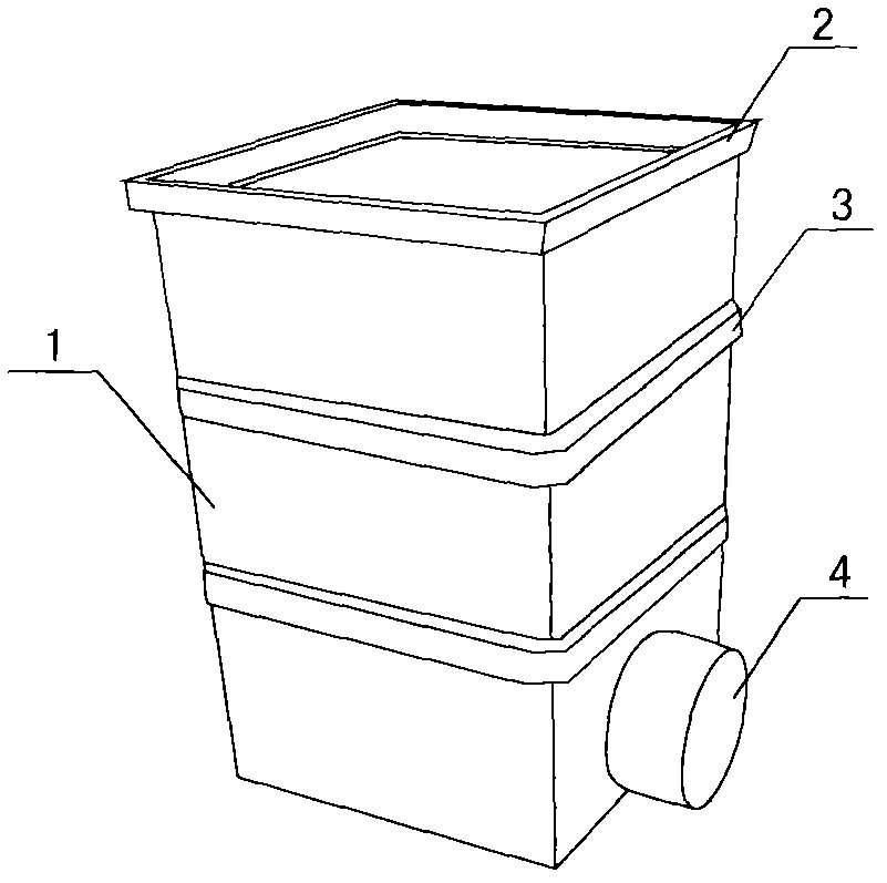
[0013] like figure 1 As shown, a resin inspection well is composed of a well body 1, a flange ring 2, a reinforcing rib 3 and a pipe joint 4, wherein the outer side of the well body 1 is evenly distributed with a reinforcing rib 3, and the lower end of the well body 1 is provided with a pipe joint 4. The blue ring 2 is socketed with the upper end of the well body 1; during specific implementation, take the preparation of 1000g of resin inspection well material as an example, first stir the resin, glass fiber, filler, colorant, and curing agent (Group A), and the various components The weight accounted for is: 500g of resin, 180g of glass fiber, 160g of filler, 10g of colorant, 75g of curing agent (group A); then mix the stirred resin with 75g of curing agent (group B) and pour it into the mold Inside, and finally demoulding, the finished product can be obtained.

[0014] The invention uses resin as the main material for manufacturing inspection wells, which can completely rep...


PUM


Abstract

The invention discloses a resin inspection well and a manufacturing method thereof. The resin inspection well comprises a well body, a flange ring, a plurality of reinforcing ribs and a pipeline joint, wherein the reinforcing ribs are evenly distributed on the outer side of the well body; the pipeline joint is arranged at the lower end of the well body; and the flange ring is sheathed with the upper end of the well body. The detailed manufacturing method comprises the steps as follows: 1, stirring resin, glass fibers, a bulking agent, a coloring agent and a curing agent (group A); 2, mixing the stirred resin with the curing agent (group B) and casting into a mold; and 3, demolding. According to the invention, the resin is used as a primary material for manufacturing the inspection well, and is mixed with the materials such as the bulking agent and the like, so that the inspection well has the effects of corrosion resistance, high-pressure resistance, aging resistance and the like; the manufactured flange ring is sleeved on the well body, so that the overall height of the inspection well can be adjusted; and in addition, the reinforcing bars enable the inspection well to bear higher pressure. Therefore, the resin inspection well provided by the invention can completely replace the existing inspection wells built by bricks and cement. As a result, the mounting period is shortened greatly, and a large amount of construction cost is saved.

Description

technical field [0001] The invention relates to a resin inspection shaft and a manufacturing method thereof. Background technique [0002] In the prior art, inspection wells are generally made of red bricks, cement, and mortar, and the whole is a rigid structure. The mortar on the inner wall is easy to fall during use, which not only hinders drainage but also makes sewage seep from the inner wall, or groundwater Infiltration from the outer wall causes incomplete diversion of rain and sewage, pollutes the water environment, and indirectly increases the water treatment pressure of the sewage treatment plant. In addition, a worker can only build one brick inspection well per day, and it will be affected by the weather. Normal construction is impossible under climatic conditions such as high temperature, severe cold, etc., and the construction period is delayed. At the same time, the overall structure of the brick inspection well is complex, which is easy to cause energy waste, ...

Claims


Application Information

Patent Timeline
IPC IPC(8): E02D29/12E03F5/02B29C45/00C08L101/00C08K13/04C08K7/14
Inventor 巢善鸣华铮
Owner 巢善鸣
Learn More