Solar cell having back surface field structures and manufacturing method thereof

A technology of solar cells and manufacturing methods, applied in the direction of final product manufacturing, sustainable manufacturing/processing, circuits, etc., capable of solving problems such as lower conversion efficiency, structural damage of the dielectric layer 12, and impact on the quality and function of the dielectric layer 12, etc. Achieve the effect of avoiding damage and improving conversion efficiency

Inactive Publication Date: 2012-12-19
MOTECH INDUSTRIES
View PDF6 Cites 3 Cited by
  • Summary
  • Abstract
  • Description
  • Claims
  • Application Information

AI Technical Summary

Problems solved by technology

[0005] However, since the aluminum glue is directly coated on the surface of the dielectric layer 12, the aluminum glue material will also diffuse and erode the dielectric layer 12 during the high-temperature sintering process, causing the structure of the dielectric layer 12 to be destroyed, and the aluminum glue will not only In addition to aluminum as the main component, it also contains many different components. For example, the glass material in it is also easy to react with the dielectric layer 12, thus affecting the quality and function of the dielectric layer 12 and reducing the conversion efficiency.

Method used


Image

  • Solar cell having back surface field structures and manufacturing method thereof
  • Solar cell having back surface field structures and manufacturing method thereof
  • Solar cell having back surface field structures and manufacturing method thereof

Examples


Embodiment Construction

[0029] The present invention will be described in detail below with reference to the accompanying drawings and embodiments. It should be noted that in the following description, similar elements are denoted by the same numerals.

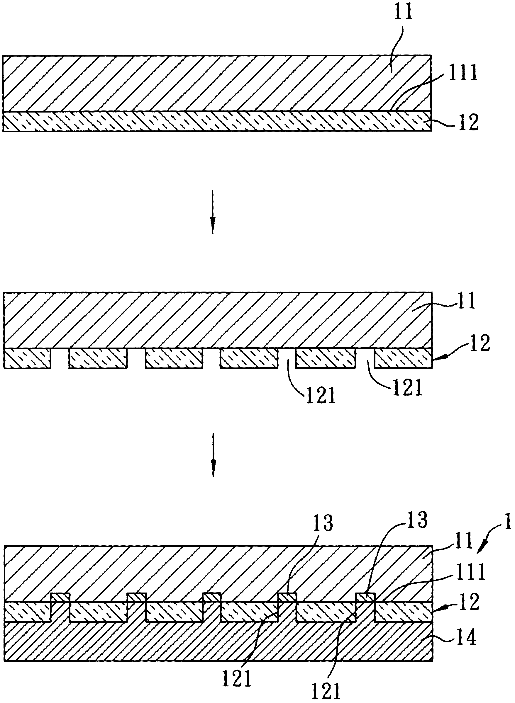
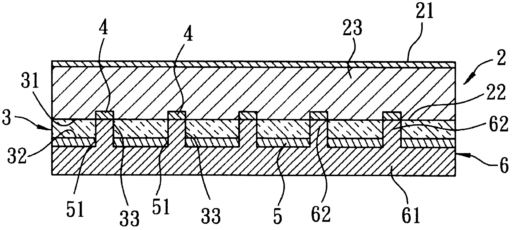
[0030] refer to figure 2 , The first preferred embodiment of the solar cell with a back electric field structure of the present invention includes: a wafer 2 , a dielectric layer 3 , a plurality of back electric field structures 4 , a metal barrier layer 5 and a conductive adhesive layer 6 .

[0031] The wafer 2 is used for converting light energy into electrical energy, and includes a light incident surface 21 and a back surface 22 opposite to the light incident surface 21 . The wafer 2 actually includes a substrate 23 with the back surface 22, an emitter layer formed on the substrate 23, an anti-reflection film and other film layers. The substrate 23 in this embodiment is a p-type silicon substrate 23, and the emitter layer For the n-type emitter...


PUM

PropertyMeasurementUnit
thicknessaaaaaaaaaa

Abstract

The invention discloses a solar cell having back surface field structures and a manufacturing method of the solar cell. The cell comprises a wafer, a dielectric layer, multiple back surface filed structures, a metal barrier layer and a conductive rubber layer. The improvement of the manufacturing method mainly lies in the fact that before forming the conductive rubber layer, the metal barrier layer is formed on the surface of the dielectric layer, and the material is silver, molybdenum, titanium-tungsten alloy, tungsten, titanium, chromium, molybdenum-tungsten alloy, platinum, gold, nickel or alloy of any combination of the materials mentioned above. By using the metal barrier layer as a surface barrier of the dielectric layer, the material of the conductive rubber layer can be prevented from diffusing in the dielectric layer in the sintering process, and further, the damage of the conductive rubber layer to the dielectric layer can be avoided, so that the dielectric layer has good quality and good effect of reducing the carrier recombination rate, and the cell conversion efficiency can be increased.

Description

technical field [0001] The invention relates to a solar cell and a manufacturing method thereof, in particular to a solar cell with a back electric field structure and a manufacturing method thereof. Background technique [0002] refer to figure 1 , is a schematic diagram of the manufacturing process of a known solar cell 1, and the structure of the solar cell 1 is first described here (please refer to figure 1 The last figure of ) mainly includes: a wafer 11 , a dielectric layer 12 , a plurality of local back surface field structures 13 (local back surface field, LBSF for short) formed on local parts of the wafer 11 , and a metal glue layer 14 . [0003] Wherein, the wafer 11 is used to convert light energy into electrical energy, and includes a p-type silicon substrate, an n-type emitter layer formed on the substrate, and film layers such as an anti-reflection film. The dielectric layer 12 is formed on the back surface 111 of the wafer 11 to reduce the rate of carrier re...

Claims


Application Information

Patent Timeline
Patent Type & Authority Applications(China)
IPC IPC(8): H01L31/0224H01L31/18
CPCY02P70/50
Inventor 黄志仁
Owner MOTECH INDUSTRIES
Why Eureka
Try Eureka