Epitaxial layer growth method for a light-emitting diode chip

A technology of light-emitting diodes and a growth method, which is applied in the field of epitaxial layer growth of light-emitting diode chips, can solve problems such as affecting the quantum efficiency of light-emitting diode chips and reducing the quality of light-emitting diode chips, so as to improve crystal quality and internal quantum efficiency, increase lateral Growth effect, effect of reducing defect density

Active Publication Date: 2015-12-09
HC SEMITEK CORP
View PDF2 Cites 0 Cited by
  • Summary
  • Abstract
  • Description
  • Claims
  • Application Information

AI Technical Summary

Problems solved by technology

[0005] Due to the large lattice constant and thermal expansion coefficient mismatch between the epitaxial layer and the sapphire substrate, a large number of dislocations and defects will be generated during the growth of the epitaxial layer. Errors and defects will extend from the substrate layer to the surface of the epitaxial layer, with a density as high as 1×10 10 / cm 3 , which affects the internal quantum efficiency of the light-emitting diode chip and reduces the quality of the light-emitting diode chip

Method used


Image

  • Epitaxial layer growth method for a light-emitting diode chip
  • Epitaxial layer growth method for a light-emitting diode chip

Examples


Embodiment 1

[0025] An embodiment of the present invention provides a method for growing an epitaxial layer of a light emitting diode chip, the method comprising:

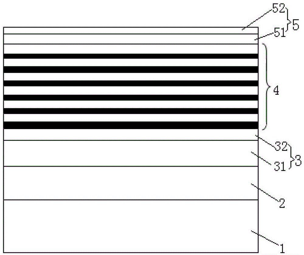
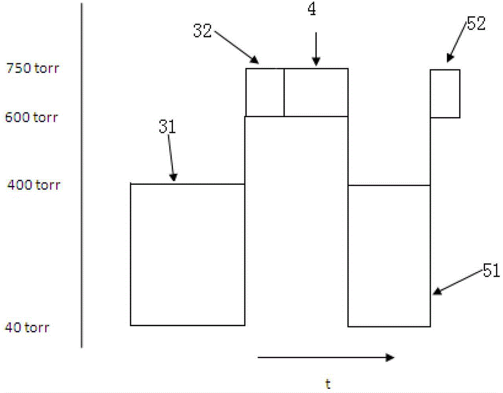
[0026] U-type GaN layer 2, n-type layer 3, quantum well active region layer 4, and p-type layer 5 are sequentially grown on substrate 1 by MOCVD method, such as figure 2 As shown, wherein, the growth pressure of the quantum active region layer 4 is 600-750 torr.

[0027] In specific implementation, this method can be realized through the following steps:

[0028] Step 101: Place the crystal-oriented sapphire substrate on a graphite disk and send it into the reaction chamber, heat the sapphire substrate to 1060° C. for 5 minutes.

[0029] Step 102: growing a 2um thick undoped GaN layer 2 under a low pressure of 200torr.

[0030] Step 103: growing a Si-doped n-type GaN carrier layer 31 with a thickness of 2 um under a low pressure of 40 torr.

[0031] Step 104: growing a Si-doped n-type GaN contact layer 32 with a thickness o...

Embodiment 2

[0038] An embodiment of the present invention provides a method for growing an epitaxial layer of a light emitting diode chip, see figure 2 , the method includes:

[0039] The MOCVD method is used to sequentially grow an undoped GaN layer 2, an n-type layer 3, a quantum well active region layer 4, and a p-type layer 5 on a substrate 1, such as figure 2 As shown, wherein, the growth pressure of the quantum active region layer 4 is 600-750 torr.

[0040] Preferably, the growth pressure of the n-type contact layer 32 is 600-750 torr.

[0041] Further, the growth pressure of the n-type GaN carrier layer 31 is 40-400 torr. In actual growth, in order to increase the growth speed, generally 40-400 torr is used to grow the n-type GaN carrier layer 31 . Apparently, the n-type GaN carrier layer 31 can also be grown with a high voltage of 600-750 torr, which can further increase the cracking effect of the material and reduce the defect density in the material.

[0042] It should be...


PUM


Abstract

The invention discloses a method for growth of an epitaxial layer of a light emitting diode chip and belongs to the technical field of semiconductors. The method includes: a GaN layer, an n-type layer, a quantum well active area layer and a p-type layer, which are not mixed, are sequentially grown on a substrate by a metallo-organic compound vapor deposition method. Growth pressure of the quantum well active area layer is 600-750torr. During process of growth of the epitaxial layer, material of the epitaxial layer simultaneously grows and splits, splitting effect of material of the quantum well active area layer is enhanced by setting growth pressure of the quantum well active area layer as 600-750torr, the surface of the material is roughed by high splitting effect, cross growth effect of the material is enhanced effectively, and accordingly defect density in the material is reduced, crystalline quality and internal quantum efficiency of the light emitting diode chip are increased, and luminous efficiency of the light emitting diode chip is further improved.

Description

technical field [0001] The invention relates to the technical field of semiconductors, in particular to an epitaxial layer growth method for a light emitting diode chip. Background technique [0002] Light-emitting diode chips are semiconductor wafers, which are the core components of light-emitting diodes. The light-emitting diode chip mainly includes a substrate, an epitaxial layer grown on the substrate, and electrodes arranged on the epitaxial layer. [0003] Wherein, the epitaxial layer generally includes an undoped GaN layer, an N-type layer, a multi-quantum well layer and a P-type layer. At present, most light-emitting diodes grow epitaxial layers on sapphire substrates by MOCVD (Metal-Organic Chemical Vapor Deposition, Metal-Organic Chemical Vapor Deposition) method. Wherein, when growing the epitaxial layer, the growth pressure used is 40-400 torr. [0004] In the process of realizing the present invention, the inventor finds that there are at least the following...

Claims


Application Information

Patent Timeline
Patent Type & Authority Patents(China)
IPC IPC(8): H01L33/00
Inventor 孙玉芹王江波刘榕
Owner HC SEMITEK CORP
Why Eureka
Try Eureka