Supercharge Your Innovation With Domain-Expert AI Agents!

Oscillation circuit

An oscillating circuit and circuit technology, applied in power oscillators, electrical components, generating electrical pulses, etc., can solve the problems of reducing temperature dependence, difficult to reduce consumption, difficult to adjust the temperature dependence of oscillation frequency, and reduce the temperature dependence. , the effect of reducing current consumption

Inactive Publication Date: 2012-12-19
LAPIS SEMICON CO LTD
View PDF8 Cites 4 Cited by
  • Summary
  • Abstract
  • Description
  • Claims
  • Application Information

AI Technical Summary

Problems solved by technology

There is a problem that since the external resistance is fixed in the design environment, it is impossible to adjust the temperature dependence of the reference resistance, and finally it is difficult to adjust the temperature dependence of the oscillation frequency
Furthermore, in the oscillation circuit described in Patent Document 1, the method of controlling the amount of current flowing from the inverter to the capacitor has the problem that it is difficult to achieve both low consumption and reduced temperature dependence as required.

Method used


Image

  • Oscillation circuit
  • Oscillation circuit
  • Oscillation circuit

Examples


Embodiment Construction

[0022] Hereinafter, an example of embodiment of the present invention will be described in detail with reference to the drawings.

[0023] (Composition of CR oscillation circuit)

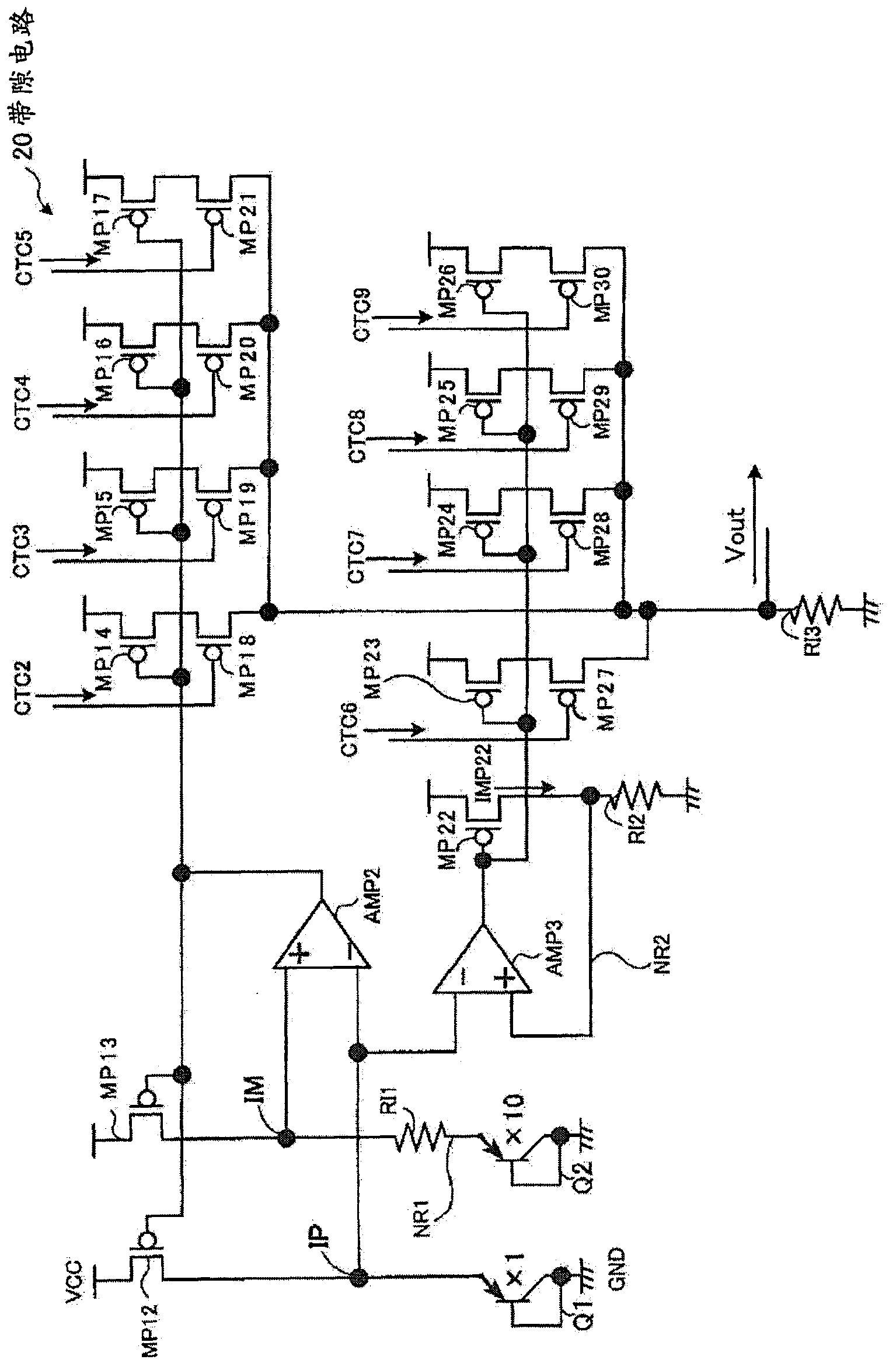
[0024] figure 1 It is a circuit diagram showing an example of the configuration of the oscillation circuit according to the embodiment of the present invention. The oscillation circuit 10 is mounted on an integrated circuit such as a CPU of a microcomputer. Such as figure 1 As shown, the oscillation circuit 10 includes: a bandgap circuit 20 that outputs an output voltage Vout whose temperature dependence is adjusted; converts the output voltage Vout of the bandgap circuit 20 into an output current Iout, and outputs a voltage of a bias current Ib based on the output current Iout - the current conversion circuit 30 ; the CR oscillation circuit 40 that operates based on the bias current Ib input from the voltage-current conversion circuit 30 .

[0025] In general, a bandgap circuit is a circuit t...


PUM


Abstract

The invention provides an oscillation circuit. The oscillation circuit can reduce temperature dependency of oscillation frequency and perform high-precision oscillation in a case that the oscillation circuit needs high-precision oscillation, and can reduce current consumption of the oscillation circuit in a case that the high-precision oscillation is not needed. The oscillation circuit includes: a band-gap circuit that outputs an output voltage adjusted for temperature dependency so as to give a constant output voltage independent of temperature; a voltage-current conversion circuit including a first variable resistor, the voltage-current conversion circuit converting an output voltage output from the band-gap circuit into an output current corresponding to the resistance of the first variable resistor and outputting a bias current based on the converted output current; and a CR oscillation circuit including a second variable resistor, a capacitor and a comparator section, the CR oscillation circuit oscillating with an oscillation frequency based on the resistance of the second variable resistor and the capacitance value of the capacitor, and the CR oscillation circuit operating according to the amperage of the bias current the comparator section has input from the voltage-current conversion circuit.

Description

technical field [0001] The present invention relates to an oscillating circuit, in particular to an oscillating circuit capable of high-precision oscillation. Background technique [0002] Conventionally, as an oscillation circuit mounted on an integrated circuit such as a central processing unit (CPU) of a microcomputer, a relatively inexpensive and high-precision CR oscillation circuit has been used instead of an expensive crystal oscillation circuit. Such as Figure 7 As shown, the CR oscillating circuit is composed of, for example, a resistor R3 , a capacitor C1 , a capacitor C2 , a comparator 4 , an inverter 5 and an inverter 6 . The oscillating frequency of the CR oscillating circuit has nothing to do with the power supply voltage, and is determined by the values ​​of the resistor R and the capacitor C. [0003] However, there is a problem that the resistance R has temperature dependence in which the resistance value varies with temperature, and the oscillation freque...

Claims


Application Information

Patent Timeline
Patent Type & Authority Applications(China)
IPC IPC(8): H03B5/04
CPCH03K3/011H03K3/0315H03B5/04H03K3/0231
Inventor 岩佐洋助
Owner LAPIS SEMICON CO LTD
Features
  • R&D
  • Intellectual Property
  • Life Sciences
  • Materials
  • Tech Scout
  • Unparalleled Data Quality
  • Higher Quality Content
  • 60% Fewer Hallucinations
Learn More