Electrical energy copy increment technology

An electric energy, incremental technology, applied in the direction of electrical components, electromechanical devices, etc., can solve the problem of no effective power and so on

Inactive Publication Date: 2013-01-02
鲍小福
View PDF0 Cites 4 Cited by
  • Summary
  • Abstract
  • Description
  • Claims
  • Application Information

AI Technical Summary

Problems solved by technology

[0003] In order to solve the problem of no effective power in the entire unit o

Method used


Image

  • Electrical energy copy increment technology
  • Electrical energy copy increment technology
  • Electrical energy copy increment technology

Examples


example 1

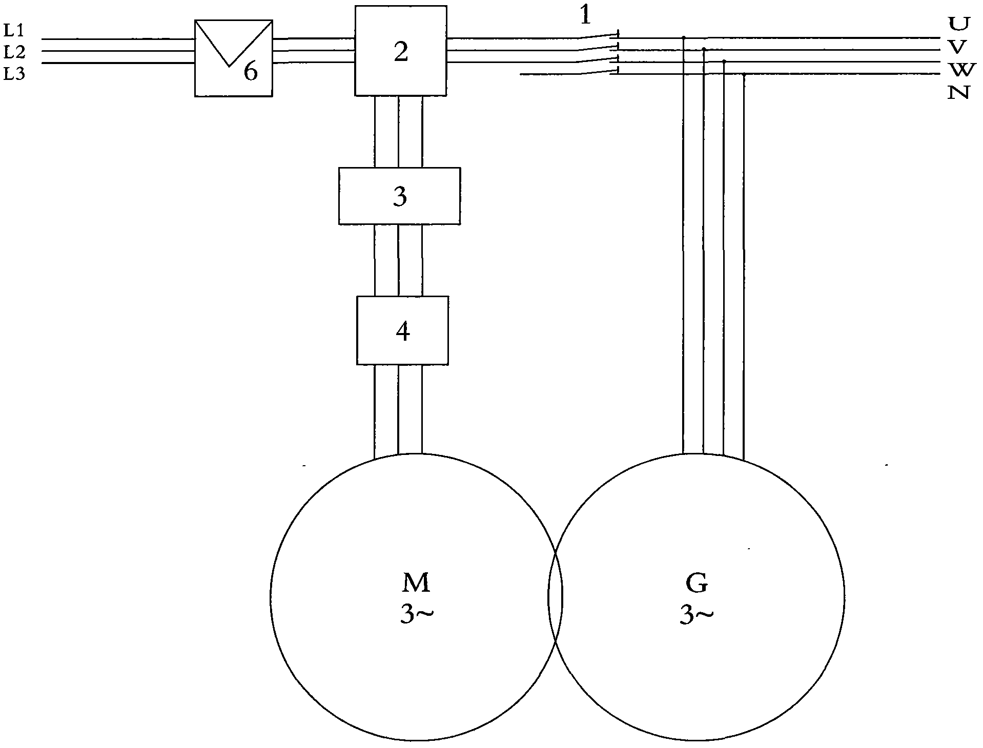
[0016] Example 1: In figure 1Among them, (1) is a normally closed switch. The external starting power is connected to the input terminal of the starter (6), the switch of the starter is turned on, the starting power passes through the starter (6), the normally closed contact of the voltage relay (2), the motor speed control system (3), and the motor protection The system (4), flows to the motor group (M) of the self-rotating unit (MG), starts the unit to run, and the power generated by the generating group (G) passes through the switch (1) to the normally open contact of the voltage relay (2) , when the power supply voltage generated by the generating set (G) rises to the setting value of the voltage relay, the voltage relay will automatically work to close the normally open contact and open the normally closed contact, and the power supply will pass through the voltage relay (2), the motor speed The control system (3), the motor protection system (4) and the motor group (M) ...

example 2

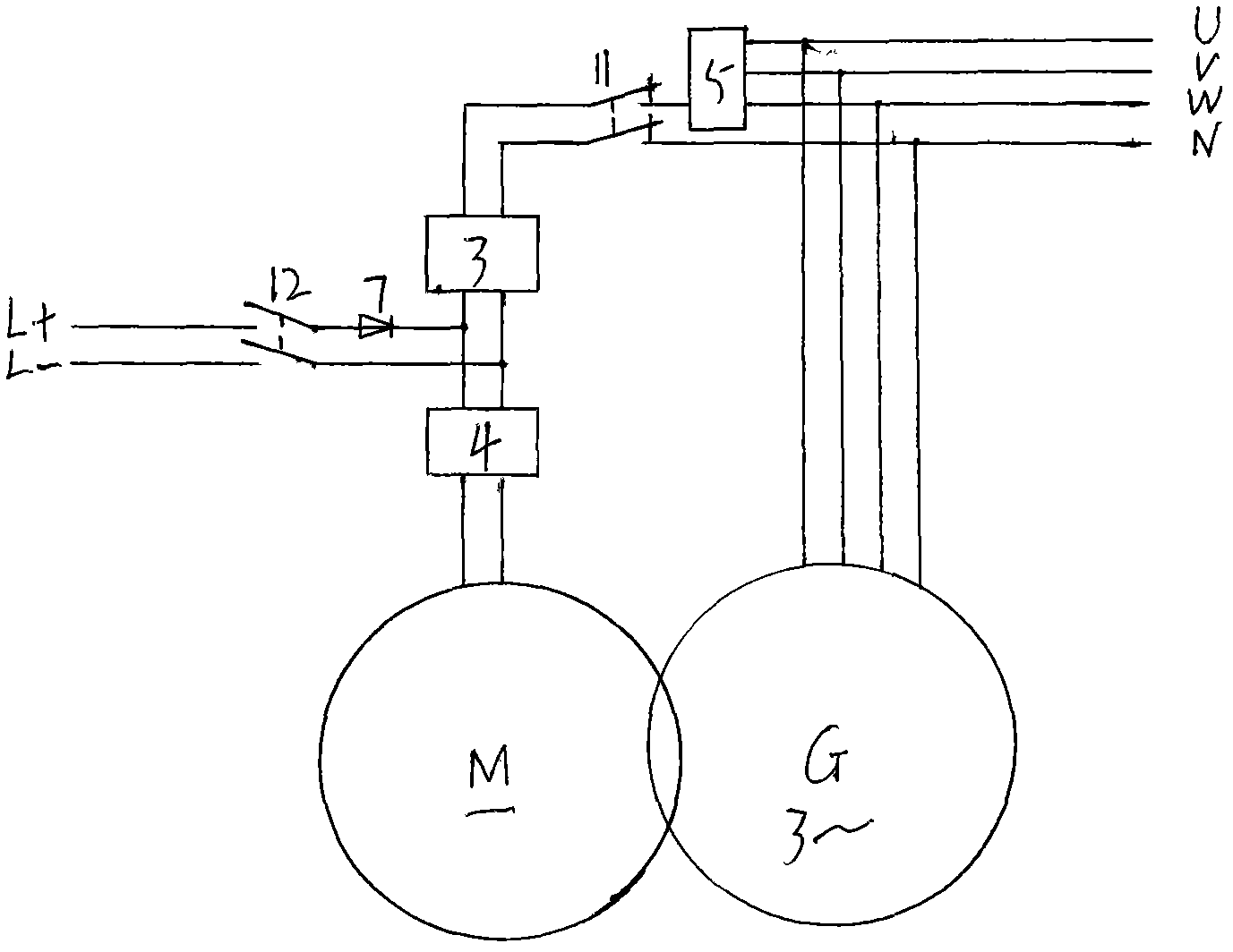
[0017] Example 2: In figure 2 Among them, (11) is a normally closed switch. The external starting power supply is connected to the input end of the switch (12), and the switch (12) is closed. The external starting power supply passes through the switch (12), the diode (7), and the motor protection system (4) to the motor group ( M) Start the unit to run, and the AC power generated by the generating set (G) is rectified into a DC power supply through the bridge rectifier system (5), and then passed through the switch (11), the motor speed control system (3), and the motor protection system (4) To the motor group (M) of the autorotation unit (MG) for self-circulation operation. When the operation of the unit can be self-circulating, the switch (12) is turned off to make the unit do self-circulating. Because the bridge rectifier system (5) has a blocking effect, the external starting power will not flow to the generating set (G) of the self-rotating unit.

example 3

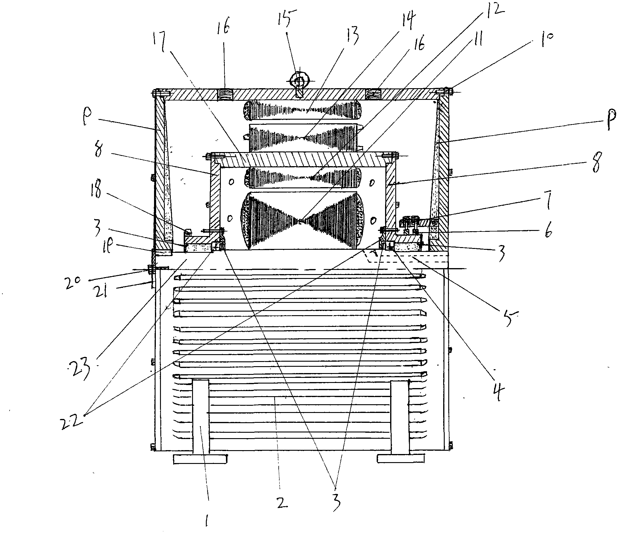
[0018] Example 3: This example is an example of using compressed air to start the operation of the self-rotating unit without starting the power supply. exist image 3 Middle: The air motor is installed on the end cover of the machine base, and the motor is driven by compressed air, so that the telescopic gear of the motor meshes with the ring gear (18) on the support plate of the sleeve swivel, driving the sleeve swivel (17) Rotating around the anti-rotation shaft (23), the rotor group (12) of the generating set on the inner wall of the pipe sleeve rotor (17) and the stator group (11) on the anti-rotation shaft (23) generate electromotive force to generate current, and its power supply current is from A circuit element (eg figure 1 , figure 2 ) to the stator group (13) of the electric group, so that the stator winding (13) of the electric group is energized to generate a magnetic field, and the rotor group (14) of the electric group cuts the magnetic field lines in the mag...


PUM


Abstract

Disclosed is an electrical energy copy increment technology. An autorotation unit serves as a generator unit. The autorotation unit is a motor group formed by a group of electric component/electric group and a group of power generating component/generator. The autorotation unit comprises a self-loop operating circuit. According to a balance theory, the output power of the power generating component/generator is necessarily higher than the input power of the electric group/motor, so that the electrical energy required by the autorotation unit for the self-loop operating can be guaranteed, and redundant effective power can still be reserved for outwards transmitting the electrical energy. The technical scheme for solving the problem of effective power includes that the stator core inner diameter of the electric group/motor is necessarily larger than that of the power generating component/generator, and the physical quantity of skill energy of a lever is converted to electrical energy by the numerical value of a radial ratio between the stator core inner diameter of the electric group/motor and the stator core inner diameter of the power generating component/generator, a mechanical equilibrium theory of a weigh beam and the lever and a mechanical skill of the lever.

Description

Technical field: [0001] The invention relates to motor and electric energy replication incremental technology. Background technique: [0002] At present, there is a motor unit in which a motor drives a generator to run together to generate electricity. Since, in the process from the input electric energy of the motor to the output electric energy of the generator, there is the problem of the energy loss of the motor unit itself, so there is a common technical prejudice among technicians that, according to the law of energy conservation, the power generation unit of the motor unit The output power of the generator / generator cannot be greater than the input power of the electric group / motor. In other words, the rated efficiency of the entire motor unit cannot exceed the base of 1. That is to say, the ratio of the output power of the generating set / generator of the electric set to the input power of the electric set / motor cannot be greater than the base number of 1. Therefor...

Claims


Application Information

Patent Timeline
IPC IPC(8): H02K53/00
Inventor 鲍小福
Owner 鲍小福
Why Eureka
Try Eureka