Gantry-movable drilling, boring and milling compound machine tool
A composite processing, drilling and boring technology, which is applied in the direction of metal processing machinery parts, metal processing equipment, manufacturing tools, etc., can solve the problems of guide rail lubrication, dust prevention and long-term durability and accuracy, and achieve simple structure and long processing length. Long-term, long-term effect
- Summary
- Abstract
- Description
- Claims
- Application Information
AI Technical Summary
Problems solved by technology
Method used
Image
Examples
Embodiment 1
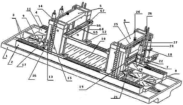
[0010] Example 1. according to figure 1 As shown, 1 is the foundation, 2 and 11 are two bases with the same structure, and 5 and 6 are two gantry frames with the same structure. Through the rack mating gear mechanism 12 meshing with the rack 4, the gantry frames 5 and 6 perform reciprocating linear motion on the linear guide rail 3. Both the linear guide rail 3 and the rack 4 are fixed on the bases 2 and 11. The bases 2 and 11 and the workbench 10 are all fixed on the foundation 1. 5 and 6 two gantry frames all have four drilling and milling head mechanisms 7 with the same structure. Drilling and milling head mechanism 7 and drilling and milling head mechanism 17 all can be loaded onto press tool table turning machine parts. Gantry 5 and 6, the lifting guide of its square beam 18 and drilling and milling head mechanism 17 is to adopt cylinder and cylinder sliding sleeve to cooperate. 8 and 9 are two rotary table mechanisms with the same structure. 10 is an extended workb...
Embodiment 2
[0011] Example 2. Said gantry frame 5 in embodiment 1, as figure 1 Shown, the portal frame 5 both sides are respectively provided with two vertical round columns 13. Reducer 14 drives leading screw 15, and leading screw 15 cooperates with double-hole cover 16, thereby makes double-hole cover 16 do linear motion up and down along round column 13. The drilling and milling head mechanism 17 is connected with the double hole sleeve 16, so that the drilling and milling head mechanism 17 moves vertically up and down. The lead screw 20 cooperates with the bottom plate 22 of the vertical knife sliding sleeve, the drilling and milling head mechanism 7 is connected with the bottom plate 22 of the vertical knife sliding sleeve, the upper and lower two linear guide rails 21 are fixed on the square beam 18, and the beam screw reducer 19 is fixed on the square beam 18 On the left and right sides, the beam lead screw reducer 19 drives the lead screw 20, so that the drilling and milling hea...
Embodiment 3
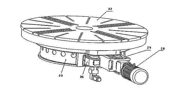
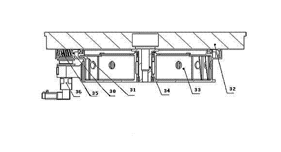
[0012] Example 3. Said rotary table mechanism 8 in embodiment 1, as figure 2 and image 3 As shown, the main reducer 29 is fixed on the side wall of the base 33, the frequency conversion motor 28 drives the main reducer 29, the main reducer 29 transmits the speed and torque to the ring gear 30, and the ring gear 30 is fixed on the workbench 32, The main shaft 34 is connected with the workbench 32, and the upper and lower parts of the large slewing bearing 31 are respectively fixed on the base 33 and the workbench 32. Therefore, the ring gear 30 transmits the rotational speed and torque to the worktable 32, and the worktable rotates at a certain rotational speed. When the workbench needs indexing, the main reducer 29 is driven to the highest gear, the frequency conversion speed regulation motor 28 stops, the indexing reducer 36 drives the indexing gear 35 to rotate, and the indexing gear 35 drives the ring gear 30 to rotate. Thus, the workbench is indexed, and the accuracy ...
PUM
 Abstract
Description
Claims
Application Information
 - R&D
- Intellectual Property
- Life Sciences
- Materials
- Tech Scout
- Unparalleled Data Quality
- Higher Quality Content
- 60% Fewer Hallucinations
Browse by: Latest US Patents, China's latest patents, Technical Efficacy Thesaurus, Application Domain, Technology Topic, Popular Technical Reports.
© 2025 PatSnap. All rights reserved.Legal|Privacy policy|Modern Slavery Act Transparency Statement|Sitemap|About US| Contact US: help@patsnap.com


