H-shaped cylinder structure for external work output connection of turbo expander

A turbo expander and output connection technology, which is applied in mechanical equipment, engine components, machines/engines, etc., can solve the problems that plague the industry and lack, and achieve the effects of simple overall structure, high degree of generalization, and good economy

Inactive Publication Date: 2013-01-09
联优机械(常熟)有限公司
View PDF9 Cites 2 Cited by
  • Summary
  • Abstract
  • Description
  • Claims
  • Application Information

AI Technical Summary

Problems solved by technology

[0004] As known in the industry, there are differences in the flow and / or pressure of turboexpanders, that is, there are differences in output power, and due to the It is necessary to rely on the transition connection device to realize the connection with the aforementioned external power absorption equipment. Therefore, turboexpanders with different output power need to be equipped with transition connection devices of different specifications that are suitable for them. Therefore, due to the large number of transition connection devices, the Manufacture, assembly, maintenance, and even storage cause trouble, and also cause waste of resources
In addition, when the blower previously fixed to the volute (also called the expander housing) of the turbo expander and connected to the worm wheel (also called the impeller) of the turbo expander needs to be replaced according to the change of application Generators or other matching equipment (also known as functional equipment), due to the constraints of the non-universal transition connection device, can only wait and see, unless it is redesigned to meet the requirements of the generator and expander. mating requirements, thereby not only increasing cost, but also time consuming
[0005]Therefore, for a long time, due to the lack of a transition connection device with a reasonable structure and a good degree of generalization for connecting the turbo expander and the external power absorption equipment, the above-mentioned The problem has been perplexing the industry all the time, and the applicant has made useful exploration and design for this reason, and has finally formed the technical scheme that will be introduced below

Method used


Image

  • H-shaped cylinder structure for external work output connection of turbo expander
  • H-shaped cylinder structure for external work output connection of turbo expander
  • H-shaped cylinder structure for external work output connection of turbo expander

Examples


Embodiment

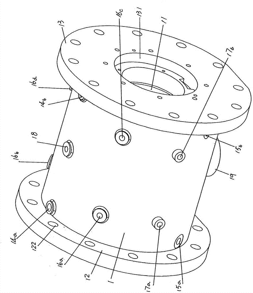
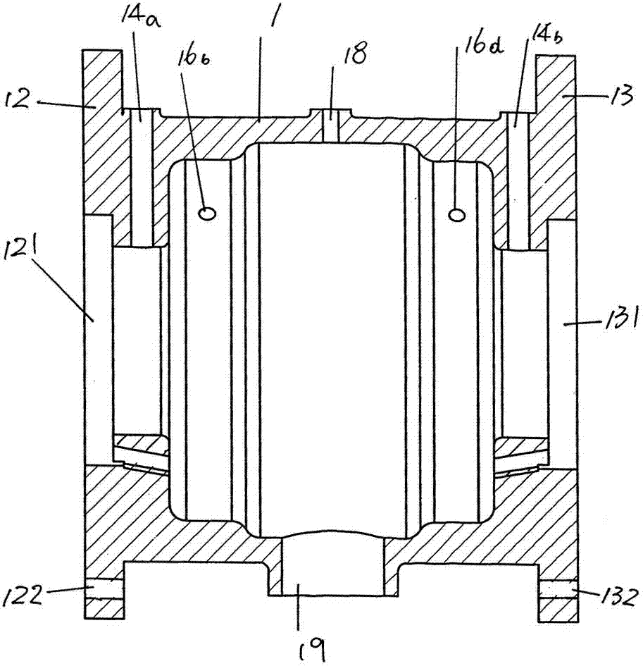
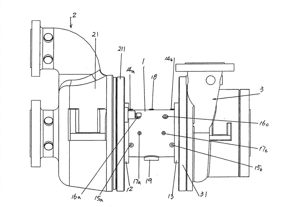
[0016] See figure 1 and figure 2 , shows a cylinder 1 with a cylinder cavity 11. Taking the position shown in the current illustration as an example, a first mating flange with a diameter larger than the diameter of the cylinder 1 is expanded at one end of the cylinder 1, that is, the left end Disc 12, on the first mating flange 12 and around the circumferential direction of mating flange 12, preferably at equal intervals, a set of image 3 The first fixed connection hole 122 connected to the volute flange 211 of the volute 21 of the schematic turbo expander 2, and the first bearing for installing the bearing is formed in the center of the first mating flange 12. Cavity 121. The other end of cylinder body 1, that is, the right end, is expanded with a second matching flange 13 having a diameter identical to that of the first matching flange 12, on the second matching flange 13 and surrounding the second The circumferential direction of the mating flange 13 is provided ...


PUM


Abstract

An H-shaped cylinder structure for external work output connection of a turbo expander belongs to low temperature equipment. The H-shaped cylinder structure comprises a cylinder, wherein a first matched connection flange and a second matched connection flange are respectively formed at two ends of the cylinder; a first bearing fit cavity and a second bearing fit cavity are formed in the middle of the first matched connection flange and the second matched connection flange; a first oil inlet connector and a second oil inlet connector are arranged on the cylinder and face to one end of the first matched connection flange and one end of the second matched connection flange; a first air inlet connector and a second air inlet connector are arranged on the cylinder and face to one end of the first matched connection flange and one end of the second matched connection flange; a first vibration measurement probe, a second vibration measurement probe, a third vibration measurement probe and a fourth vibration measurement probe are arranged on the cylinder and face to one end of the first matched connection flange and one end of the second matched connection flange; a first temperature measurement connector and a second temperature measurement connector are arranged on the cylinder and face to one end of the first matched connection flange and one end of the second matched connection flange; and a rotating speed measurement connector and an oil outlet connector communicated with a cylinder cavity are arranged on the cylinder. The H-shaped cylinder structure has the advantages of being convenient to assemble and maintain and high in universalization degree, saving materials, reducing difficulties of mold design and reducing using quantity of molds.

Description

technical field [0001] The invention belongs to the technical field of cryogenic equipment, and in particular relates to an H-shaped cylinder structure used for connecting external power output of a turbo expander. Background technique [0002] Expanders are usually divided into two categories according to their movement mode and structure: one is piston expander; the other is turbo expander. Compared with the piston expander, the turbo expander has the characteristics of large flow, simple structure, small volume, high efficiency and long operation period, so it is widely used in various cryogenic equipment. [0003] As is well known in the industry, a turbo expander is a machine that transfers energy through changes in the speed energy of gas expansion. It is limited to the absorption of examples such as generators, blowers, water pumps, superchargers, and oil brakes. There is no lack of technical information about turboexpanders in the published Chinese patent documents...

Claims


Application Information

Patent Timeline
Patent Type & Authority Applications(China)
IPC IPC(8): F01D25/28F01D25/24
Inventor 黄光宏杨仁泓王振新蒋文豪朱道祥
Owner 联优机械(常熟)有限公司
Why Eureka
Try Eureka