
Output voltage detecting circuit for frequency changer and frequency changer

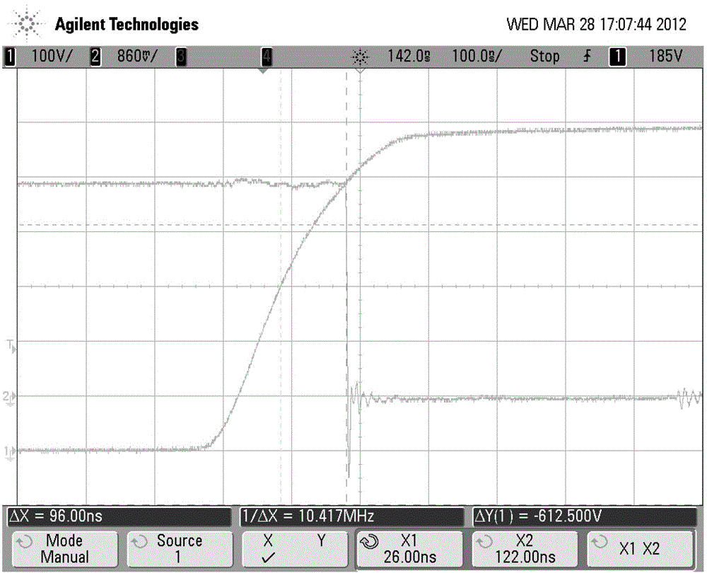
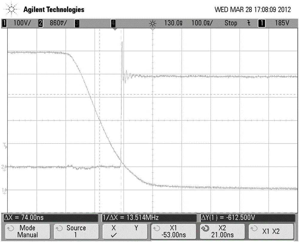
An output voltage detection, frequency converter technology, applied in the direction of voltage/current isolation, current/voltage measurement, instruments, etc., can solve the problems of the frequency converter output voltage detection is not isolated, the sampling signal is easily interfered, etc., to achieve a small transmission delay , the use of less devices, the effect of small delay

Inactive Publication Date: 2013-01-09
SHENZHEN INOVANCE TECH +1
View PDF7 Cites 5 Cited by
  • Summary
  • Abstract
  • Description
  • Claims
  • Application Information

AI Technical Summary

Problems solved by technology

[0004] The technical problem to be solved by the present invention is to provide a frequency converter output voltage detection circuit and frequency converter

Method used


Image

  • Output voltage detecting circuit for frequency changer and frequency changer
  • Output voltage detecting circuit for frequency changer and frequency changer
  • Output voltage detecting circuit for frequency changer and frequency changer

Examples


Embodiment Construction

[0018] In order to make the object, technical solution and advantages of the present invention clearer, the present invention will be further described in detail below in conjunction with the accompanying drawings and embodiments. It should be understood that the specific embodiments described here are only used to explain the present invention, not to limit the present invention.

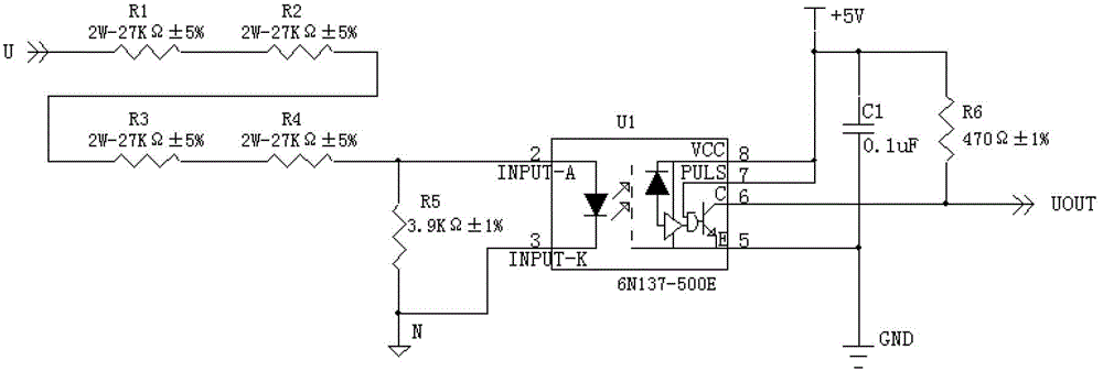
[0019] The invention adopts the high-speed isolation optocoupler to realize the strong electric isolation and the output voltage detection of the frequency converter. Specifically, the primary input signal of the high-speed isolated optocoupler is the voltage between the inverter output phase line (U / V / W phase output line) and the negative DC bus N, and the secondary output signal of the high-speed isolated optocoupler is Uout.

[0020] Such as figure 1 Shown is a schematic diagram of an embodiment of the frequency converter output voltage detection circuit of the present invention. This embodimen...


PUM


Abstract

The invention provides an output voltage detecting circuit for a frequency changer. The output voltage detecting circuit comprises a high-speed isolation optocoupler, a current-limiting resistor and a shunting resistor, wherein an anode of an input end of the high-speed isolation optocoupler is connected with an output phase line of the frequency changer through the current-limiting resistor, and a cathode of the input end of the high-speed isolation optocoupler is connected with a negative direct current bus of the frequency changer; two ends of the shunting resistor are respectively connected with the anode and the cathode of the input end of the high-speed isolation optocoupler; and an output detection signal of the high-speed isolation optocoupler is transmitted into a main control chip to be processed. The invention further provides the frequency changer comprising the output voltage detecting circuit. The invention realizes the strong electricity isolation through the high-speed isolation optocoupler, and is suitable for the detection of the output voltage of the frequency changer where the main control chip is placed at a weak current side.

Description

technical field [0001] The invention relates to the field of output voltage detection, and more specifically relates to a frequency converter output voltage detection circuit and a frequency converter. Background technique [0002] In the frequency converter, it is often necessary to perform real-time detection of the output three-phase voltage to meet the needs of monitoring and control. The existing methods generally use a megohm-level resistor to connect between the output terminal of the frequency converter and the negative bus. , realized by way of resistive voltage divider and comparison circuit. [0003] However, this detection method does not carry out isolation. If the main control chip is set on the weak current side of the secondary side in the overall scheme of the frequency converter, this detection method cannot be applied. In addition, the detection signal on the high-voltage side in the above circuit is easily disturbed and not very stable. Contents of the...

Claims


Application Information

Patent Timeline
IPC IPC(8): G01R15/22G01R19/00
Inventor 曾金芳
Owner SHENZHEN INOVANCE TECH
Learn More