Radio frequency automatic gain control amplifier

A technology of automatic gain control and gain amplifier, applied in the field of radio frequency communication, can solve the problems of not meeting high linearity requirements, not considering radio frequency gain, and partial saturation of radio frequency

Active Publication Date: 2013-01-09
杭州中科微电子有限公司
View PDF2 Cites 44 Cited by
  • Summary
  • Abstract
  • Description
  • Claims
  • Application Information

AI Technical Summary

Problems solved by technology

[0005] There are many disadvantages in the prior art controllable gain amplifier: first, the traditional control method adopts the scheme of controlling the intermediate frequency adjustable gain amplifier, which can only be suitable for the situation where the dynamic range of the input signal is small, and is not suitable for applications with large dynamic range input conditions
Second, the traditional design does not consider that the RF gain can be adjusted. The actual problem is that when the input signal is large, it is easy to saturate the RF part, and the intermediate frequency control alone cannot meet the existing design requirements.
Third, the traditional control method is mainly based on the requirement of reducing the noise figure of the system to set the front-end gain as a fixed size. However, the fixed RF front-end cannot meet the high linearity requirements, and the fixed gain will worsen the signal-to-noise ratio of the RF receiver system, which will eventually affect the system performance.
[0009] The present invention will abandon the problem that the traditional structure cannot deal with the saturation of the radio frequency amplifier due to too large input signal, and proposes a radio frequency automatic gain control amplifier. The signal is amplified, while the front end provides low noise, the excessive signal is reduced, and the linearity of the system is improved, the circuit overhead and power consumption are reduced, the performance of the system is improved, and the sensitivity of the RF receiver is improved, and the power of the device can also be reduced. Consumption and volume, saving cost

Method used


Image

  • Radio frequency automatic gain control amplifier
  • Radio frequency automatic gain control amplifier
  • Radio frequency automatic gain control amplifier

Examples


no. 1 example

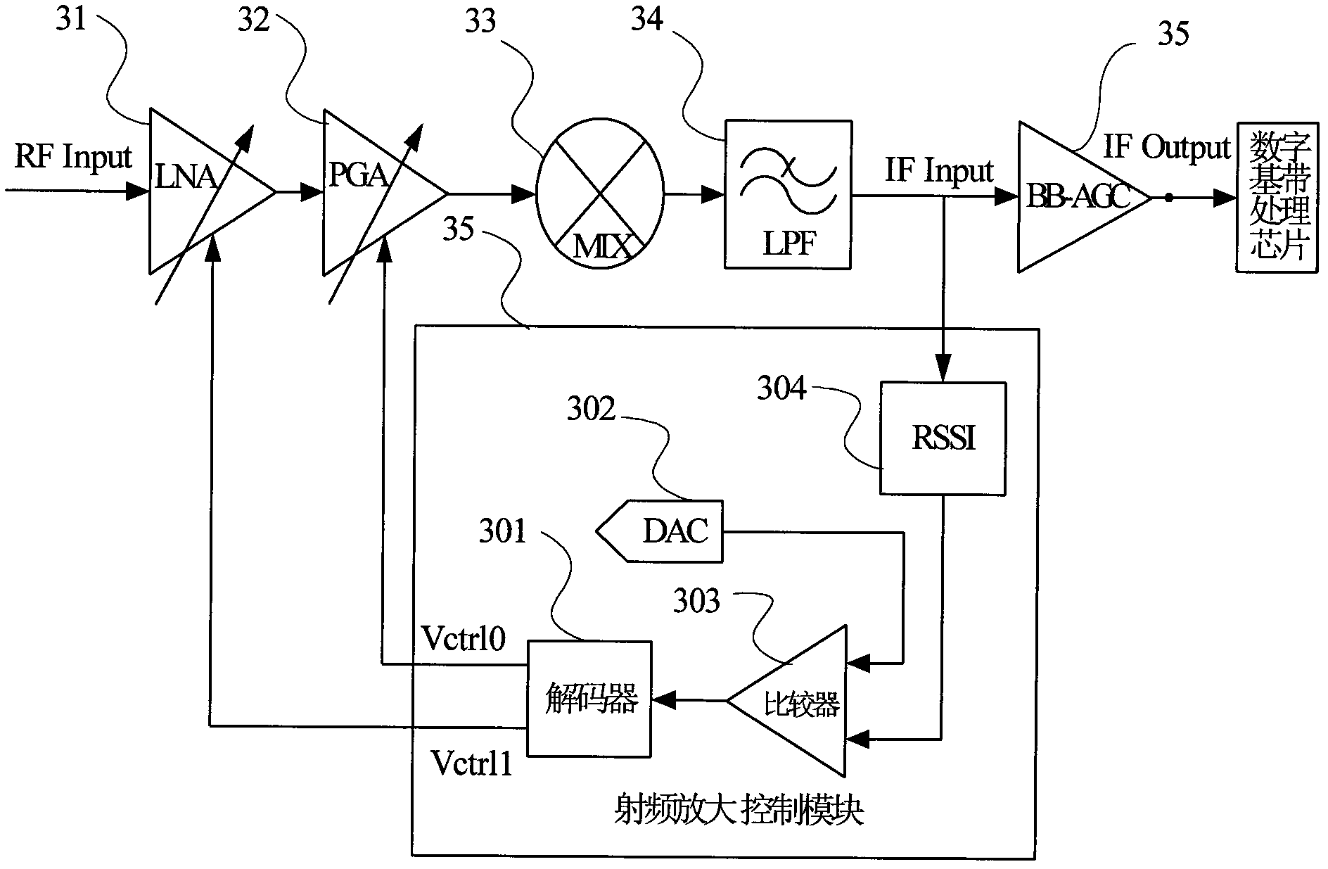
[0057] image 3 A circuit configuration block diagram of a radio frequency automatic gain control amplifier according to an embodiment of the present invention is given. to combine image 3 The implementation process of the automatic gain control mode in the present invention is described. The radio frequency input signal RFinput input gain is adjustable to the low-noise amplifier 31, through the amplification of the gain-adjustable low-noise amplifier 31, it is input to the radio frequency adjustable gain amplifier 32, and the amplified signal output by the adjustable gain amplifier 32 is in the down-conversion mixer 33 and this The vibration signal is frequency-converted into a radio frequency signal including an intermediate frequency signal, and the radio frequency signal is filtered out by a low-pass filter 34 to output an intermediate frequency signal IFoutput. On the other hand, the intermediate frequency output signal IFoutput is compared with the reference voltage g...

no. 2 example

[0059] Figure 4 A radio frequency automatic gain control amplifier according to an embodiment of the present invention is given. The embodiment is a circuit block diagram of a radio frequency automatic gain control amplifier which is applied to a digital TV radio frequency front-end chip according to the present invention. Composed of 41 gain adjustable low noise amplifier, 42 RF adjustable gain amplifier, 44, 45 down conversion mixer, 46, 47 low pass filter, 51 strength detection circuit RSSI and 43 RF automatic gain digital controller to form a radio frequency automatic gain control loop, the input signal V INN Input to the gain-adjustable low-noise amplifier 41, through the amplification of the gain-adjustable low-noise amplifier 41, input to the radio frequency adjustable gain amplifier 42, through the amplification of the radio frequency adjustable gain amplifier 42, then through the frequency conversion of the down-conversion mixer 44 to The intermediate frequency, the...

no. 3 example

[0063] Figure 6a It is a block diagram of the circuit structure of the signal strength detector of the second embodiment of the present invention, and the output signal of the strength detection circuit of the application embodiment of the present invention is compared with the VH and VL signals to generate a composition block diagram of the digital control signal. VH and VL provide the comparison voltage required by the comparator 62 to realize partition determination. The three input terminals of the comparator 62 are respectively from the output voltage of the amplitude detection circuit 61 and the VH and VL voltages output by the DAC. The output signal of the amplitude detection circuit 61 and the VH and VL reference voltage signals generated by the ADC digital-to-analog converter 63 are simultaneously input to the three input terminals of the comparator 62, and the comparator 62 gives 2-bit output signal code. Table 1 is the output signal code table of 2 bits of the com...


PUM


Abstract

The invention discloses a radio frequency automatic gain control amplifier. The radio frequency automatic gain control amplifier comprises a radio frequency receiving unit, a radio frequency amplifier control unit and an intermediate frequency amplifier, wherein the radio frequency receiving unit is composed of an adjustable low noise amplifier (LNA), a programmable gain amplifier (PGA), a down-conversion frequency mixer and a low-pass filter; the radio frequency amplifier control unit comprises a signal strength detector, a DAC (digital-to-analog converter), a comparator and a decoder; the signal strength detector is used for detecting the strength of an intermediate frequency signal; a comparator circuit is used for comparing an output signal of the signal strength detector with a fixed comparing level output from the DAC so as to output a comparison result; the decoder is used for inputting the comparison result into a gain control digital module and outputting a digital control signal so as to carry out the feedback control to the signal at the front end of the radio frequency, so that the gains of the LNA and the PGA are controlled, the signal to noise ratio of a receiving system is increased, and the requirements on dynamic ranges and high linearity of an input signal are met. The automatic gain control amplifier can be used in various radio frequency receiving chips flexibly, and particularly is applicable to radio frequency front-end circuit which has a wider input range of a radio frequency signal.

Description

Contents of the invention [0001] The invention belongs to the technical field of radio frequency communication, and relates to a radio frequency automatic gain control adjustment circuit mode, in particular to a radio frequency automatic gain control amplifier, which adopts a different gain adjustment mode than the traditional one, and is suitable for a radio frequency receiver receiving signals with a large dynamic range. Background technique [0002] In recent years, with the continuous emergence of new technologies in the field of information technology and the continuous progress of technology, the input signal range of various receiver systems has changed greatly compared with the original ones. Interference is becoming more and more serious. For applications with weak input and large interference, the receiver needs to provide a large input range and dynamic range. [0003] As we all know, when different RF signals work at the same time, interference signals from other...

Claims


Application Information

Patent Timeline
Patent Type & Authority Applications(China)
IPC IPC(8): H03F1/26
Inventor 何晓丰
Owner 杭州中科微电子有限公司
Why Eureka
Try Eureka