Well type high-temperature resistance furnace for heat treatment of PAN (polyacrylonitrile) based carbon felt

A high-temperature resistance furnace and carbon felt technology, which is applied in the field of high-temperature industrial furnaces, can solve problems such as poor heat shielding, poor heat preservation, and complex structure of heating elements, and achieve the effects of easy maintenance and replacement, reasonable layout, and simple structure

Active Publication Date: 2014-04-16
XIAN KANGBEN MATERIAL
View PDF2 Cites 0 Cited by
  • Summary
  • Abstract
  • Description
  • Claims
  • Application Information

AI Technical Summary

Problems solved by technology

[0009] In order to overcome the disadvantages of complex structure of heating element, poor heat shielding and poor heat preservation in the prior art, the present invention proposes a well-type high-temperature resistance furnace for heat treatment of PAN-based carbon felt

Method used


Image

  • Well type high-temperature resistance furnace for heat treatment of PAN (polyacrylonitrile) based carbon felt
  • Well type high-temperature resistance furnace for heat treatment of PAN (polyacrylonitrile) based carbon felt
  • Well type high-temperature resistance furnace for heat treatment of PAN (polyacrylonitrile) based carbon felt

Examples


Embodiment Construction

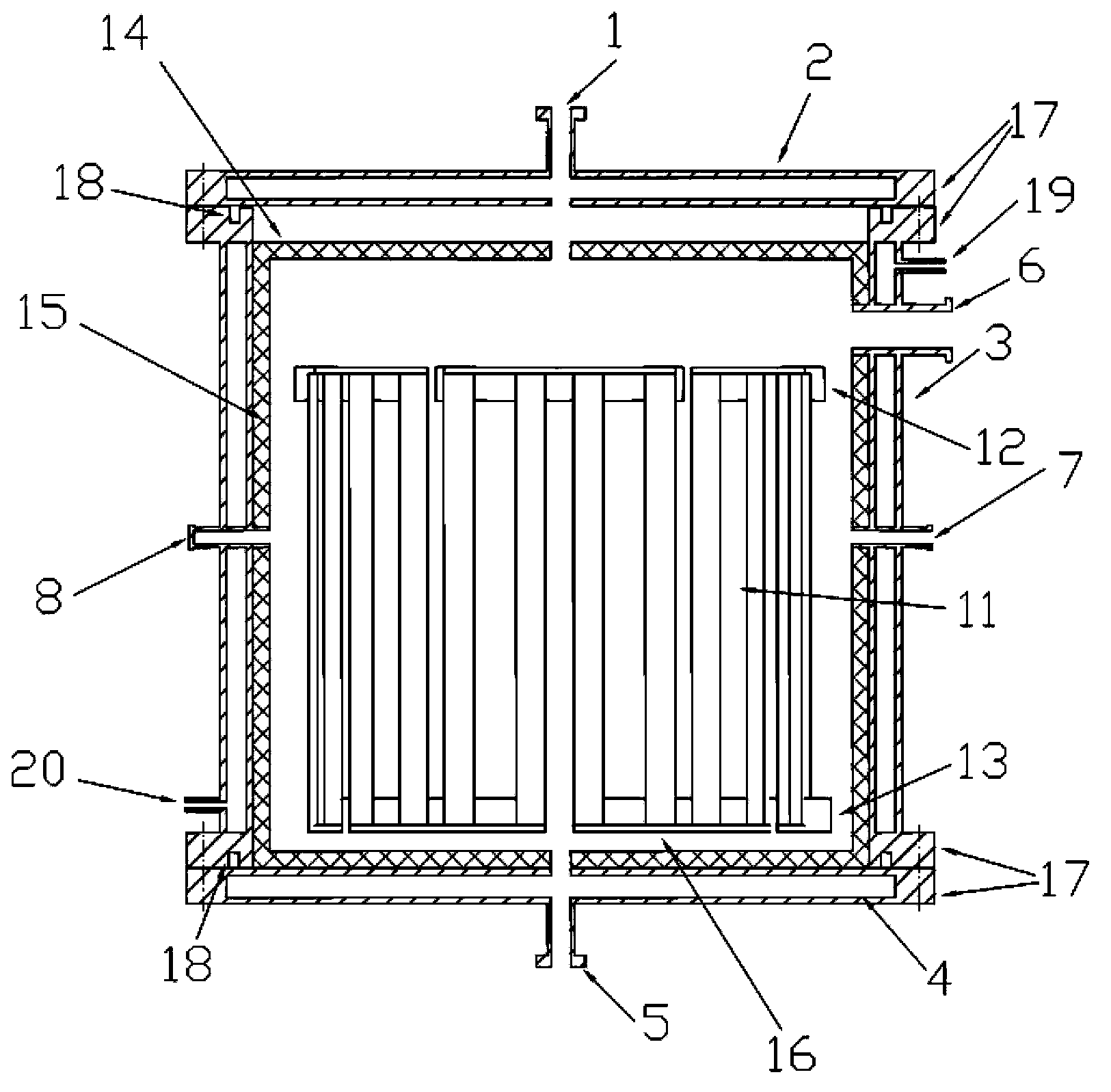
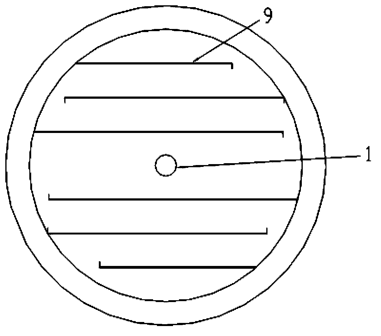
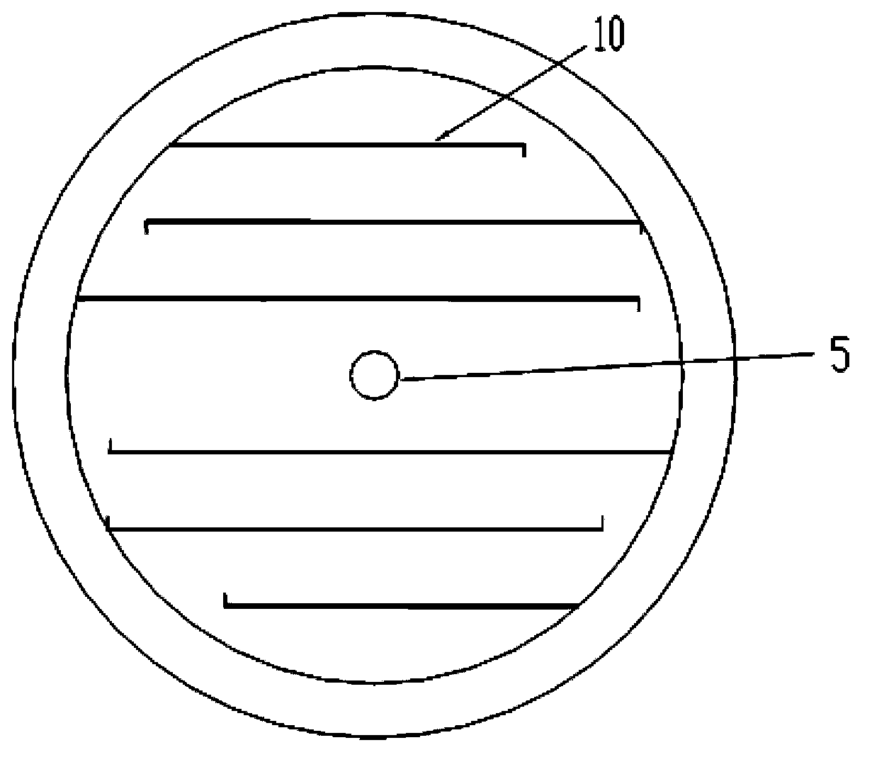
[0029] This embodiment is a device for heat treating PAN-based carbon felt, including an upper circulating water tank 2 , a furnace body 3 , a lower circulating water tank 4 , and a heating element 16 . Described body of heater has insulation layer 15, and upper insulation cover 14 is arranged on body of heater top. The heating element 16 is located in the furnace body and is supported on the furnace floor by high alumina bricks and electrodes. The upper circulating water tank 2 is placed on the upper surface of the upper insulation cover 14, and the lower circulating water tank 4 is located at the lower end of the body of heater 3, and is fixedly connected with the upper end and the lower end of the body of heater respectively by the flange 17. An insulating layer made of carbon felt is laid on the bottom plate of the furnace body. The upper part of the furnace body 3 has a furnace body exhaust port 6, and the furnace body 3 is connected with a vacuum system and a waste disc...


PUM

PropertyMeasurementUnit
heightaaaaaaaaaa
thicknessaaaaaaaaaa

Abstract

The invention discloses a well type high-temperature resistance furnace for the heat treatment of a PAN (polyacrylonitrile) based carbon felt. A heating body is placed at a center position in a furnace body; an upper circulation water tank is fixed at the upper surface of an upper heat insulation cover; and a lower circulation water tank is fixed at the lower end of the furnace body. The graphite plates of the heating body and annular graphite connection plates are arranged via the way that every two are connected in parallel and every four are connected in series, and are connected in a triangular shape by three electrodes. A water channel is arranged in the upper circulation water tank and the lower circulation water tank. The housing of the furnace body is an interlayer; and the interlayer space forms a channel of circulation water. With the adoption of the heating body, the temperature difference of a hearth uniform temperature zone ranges from 10 degrees centigrade below zero to 10 degrees centigrade. The circulation water of the cover and the bottom of the furnace body and the furnace body can uniformly and directionally flow, so that the heat radiation of the hearth can be effectively shielded, and the outer wall temperature of the furnace body is not higher than 25 degrees centigrade. With the adoption of the heat insulation layer in the furnace body, the hearth can be effectively heated, so that energy consumption is reduced; and the channel, which is simple in structure and reasonable to arrange, is convenient to maintain and exchange.

Description

technical field [0001] The invention relates to a high-temperature industrial furnace, in particular to a well-type high-temperature resistance furnace. Background technique [0002] Using PAN-based flat felt as raw material, the carbon felt is made by pre-oxidation and carbonization at 900°C, and then the carbon felt is further carbonized by heat treatment at 1600-1800°C to obtain a high-temperature felt. The invention is used for heat treatment of PAN-based carbon felt at 1600-1800°C. The advantages of high temperature felt are: ablation resistance, corrosion resistance, high purity, high carbon content, no volatilization at high temperature, small thermal conductivity, and no deformation at high temperature. Widely used in: insulation materials for vacuum furnaces (especially monocrystalline silicon furnaces) and inert gas furnaces, filter materials for hot gases, liquids, and molten metals, porous electrodes for fuel cells, catalyst carriers, and corrosion-resistant con...

Claims


Application Information

Patent Timeline
Patent Type & Authority Patents(China)
IPC IPC(8): F27B1/09F27D11/02F27B1/12F27B1/14F27B1/24
Inventor 王海涛许东葛光涛张鹏王华
Owner XIAN KANGBEN MATERIAL
Why Eureka
Try Eureka