Stator for electric rotary machine and fabricating method of the same

A technology for rotating electric machines and manufacturing methods, which is applied in the direction of manufacturing motor generators, manufacturing stator/rotor bodies, electromechanical devices, etc., and can solve the problems of reduced insulation, copper-erosive rotor torque loss, and small contact area of ​​conductors. Achieve the effects of increasing the contact area, reducing equipment costs, and improving production efficiency

Active Publication Date: 2013-01-23
HONDA MOTOR CO LTD
View PDF5 Cites 18 Cited by
  • Summary
  • Abstract
  • Description
  • Claims
  • Application Information

AI Technical Summary

Problems solved by technology

However, in the case of oil cooling, the insulation performance may be reduced due to moisture contained in the insulating oil, and there are problems such as corrosion of copper, and torque loss of the rotor due to viscous resistance of the insulating oil.
[0009] In addition, when the usual cooling method of cooling through the stator core is used for water cooling, there is a problem that the heat dissipation path becomes long, the thermal resistance cannot be suppressed, and it is difficult to obtain the desired cooling performance.
In addition, in the cooling method in which the water cooling jacket is arranged at the transition part of the coil, there is also the problem that the contact area with the conductor is small.
[0010] In addition, in a conventional rotating electrical machine in which coils are produced by winding windings on the teeth of the stator core,

Method used


Image

  • Stator for electric rotary machine and fabricating method of the same
  • Stator for electric rotary machine and fabricating method of the same
  • Stator for electric rotary machine and fabricating method of the same

Examples


Embodiment Construction

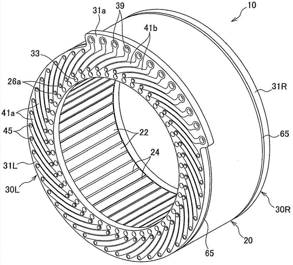
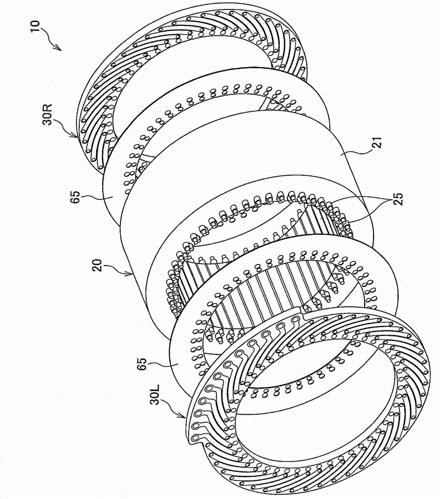
[0102] Hereinafter, embodiments of the present invention will be described based on the drawings. It should be noted that the drawings are viewed along the direction of the symbols.

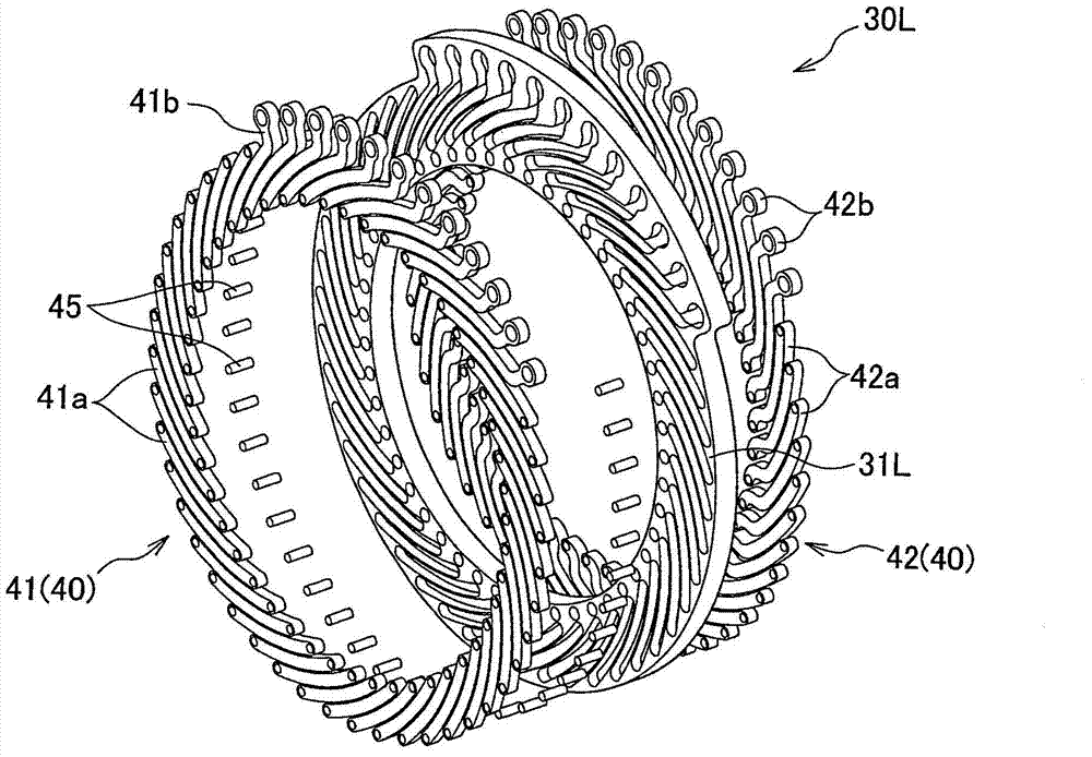
[0103] Such as figure 1 , figure 2 and Figure 5 As shown, the stator 10 of the rotating electrical machine according to this embodiment includes a stator core assembly 20 and a pair of base plate assemblies 30L, 30R. The base plate assemblies 30L, 30R are arranged and assembled on both sides of the stator core assembly 20 . An insulating sheet 65 such as a silicon wafer is arranged between the stator core assembly 20 and the base plate assemblies 30L, 30R to insulate the stator core assembly 20 from the base plate assemblies 30L, 30R.

[0104] The stator core assembly 20 includes a stator core 21 and a plurality (48 in the embodiment shown in the figure) of coil bars 25 .

[0105] The stator core 21 is formed by laminating, for example, a plurality of punched silicon steel sheets, and inclu...


PUM


Abstract

The invention provides a stator for an electric rotary machine which can be built up without using exclusive equipment and which has superior mass-production properties and a fabrication method of the same. The stator (10) includes: a stator core assembly (20) formed by a stator core (21) and a plurality of coil bars (25); and a pair of base plate assemblies (30L, 30R) formed by base plates (31L, 31R) and a plurality of connection coils (40) and arranged at two sides of the stator core assembly (20).

Description

technical field [0001] The present invention relates to a stator of a rotating electrical machine mounted in an electric vehicle, a hybrid vehicle, and the like, and a method for manufacturing the same. Background technique [0002] Conventionally, there is known a stator of a rotating electrical machine in which coils are formed by winding windings on teeth of a stator core. In addition, as the stator of other rotating electric machines, there is also known a stator configured as follows: After inserting a plurality of segments (segments) composed of electric conductors formed in a U-shape using segmented coils into the slots of the stator core, inserting the legs A part is bent, and the ends of the segments are joined together to form a coil (for example, refer to Patent Documents 1 and 2). [0003] [Patent Document 1] Japanese Patent Laid-Open No. 2003-158840 [0004] [Patent Document 2] Specification of US Patent No. 6894417 [0005] However, in a conventional rotatin...

Claims


Application Information

Patent Timeline
IPC IPC(8): H02K1/12H02K1/16H02K3/04H02K3/28H02K15/02
CPCH02K3/28H02K3/50H02K3/345H02K3/12H02K15/0414H02K9/22H02K3/505Y10T29/49071H02K9/227
Inventor 贵志武辉壹岐友贵
Owner HONDA MOTOR CO LTD
Why Eureka
Try Eureka