

Super-narrow-gap electric arc welding device for butting steel rails
An arc welding and narrow gap technology, applied in arc welding equipment, electrode support devices, auxiliary devices, etc., can solve problems affecting the safety of locomotive operation, wide heat-affected zone of base metal, strong vibration and noise, etc., and achieve good joint mechanics performance, less weld filler metal, and faster cooling
Inactive Publication Date: 2013-01-30
LANZHOU UNIVERSITY OF TECHNOLOGY
View PDF7 Cites 14 Cited by
- Summary
- Abstract
- Description
- Claims
- Application Information
AI Technical Summary
Problems solved by technology
The several rail butt joint methods introduced above generally have the problems of large heat input and wide heat-affected zone of the base metal.
The heat-affected zone will weaken the joints, causing partial depression of the rail contact surface during the use of the rail, causing strong vibration and noise, reducing the life of the rail, and affecting the operating safety of the locomotive
Method used
View moreImage
Smart ImageViewing Examples

Examples
Embodiment Construction
Login to View More PUM
| Property | Measurement | Unit |
|---|---|---|
| diameter | aaaaa | aaaaa |
Abstract
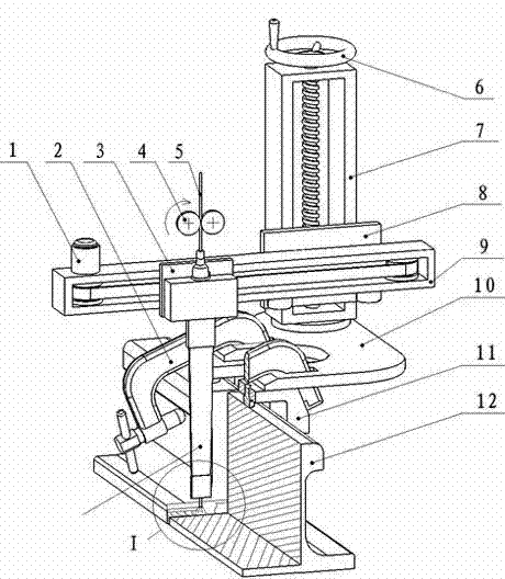
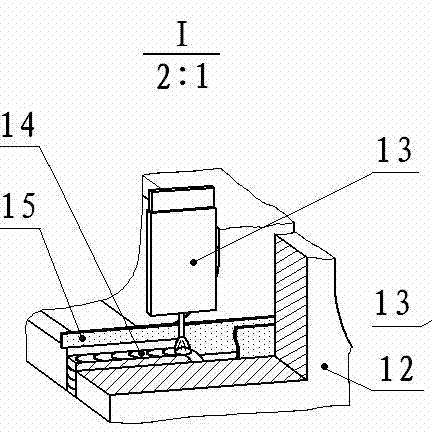
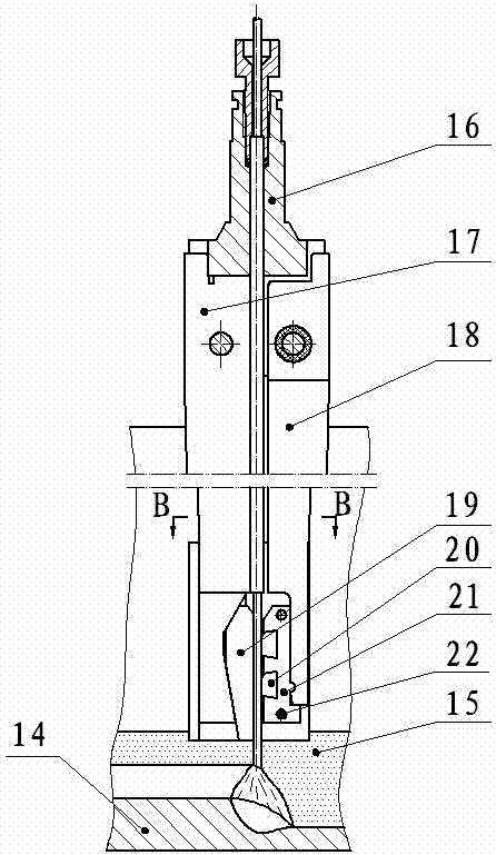
The invention discloses a super-narrow-gap electric arc welding device for butting steel rails. The steel rails (12) are fixed on positioning blocks (11) under a fixed plate (10) through a pair of C-shaped clamp forceps (2); one end of a clamp is contacted with the tread planes and the guide planes of the steel rails through a horizontal plane, and the other end of the clamp is contacted with the tread planes and the guide planes of the steel rails by a cylindrical plane; the centering of the steel rails (12) is ensured by the two positioning blocks (11); a guide rail for driving a welding gun (13) to move is installed on the fixed plate (10); the welding gun (13) is fixed on a horizontal slide block (3) and moves horizontally through a horizontal guide rail (9) during a welding process; after one steel rail is welded, the height of the welding gun is adjusted by adjusting an adjusting handle (6) on a vertical guide rail according to the height of a weld bead; and a welding flux piece (15) put at the root of a groove is kept in adhesion to a side wall and the root of the groove.
Description
technical field [0001] The invention relates to an ultra-narrow gap welding device, which is suitable for on-site welding of rail butt joints. Background technique With the construction of high-speed railways, the production and on-site welding of seamless steel rails has become an important task. Restricted by transportation and other conditions, under normal circumstances, rail welding factories weld shorter rails into long rails of 180-500 m, and then transport them to the site to weld them into seamless lines. At present, there are mainly the following welding methods for on-site welding of rails: mobile flash butt welding, gas pressure welding, arc welding, and thermite welding. Flash butt welding is to use a butt welding machine to contact the welding surface of the workpiece to be welded. Through a low-voltage strong current, the metal becomes soft under the action of resistance heat, and then quickly applies an axial upsetting force to form a butt joint; gas pres...
Claims
Login to View More Application Information
Patent Timeline
 Patent Type & AuthorityApplications(China)
IPC IPC(8): B23K9/02B23K9/173B23K9/28B23K9/32B23K37/02
Inventor朱亮周超符平坡
OwnerLANZHOU UNIVERSITY OF TECHNOLOGY