Flying ash processing device of fluidized bed incinerator

A treatment device and incinerator technology, applied in the direction of incinerators, combustion methods, combustion types, etc., can solve the problems of reducing the concentration of pollutants, the impact of cement clinker strength, and reducing the amount of fly ash emissions, so as to improve thermal economy performance, realize resource utilization, and reduce processing costs

Active Publication Date: 2013-01-30
WUXI GUOLIAN ENVIRONMENTAL SCI & TECH
View PDF11 Cites 8 Cited by
  • Summary
  • Abstract
  • Description
  • Claims
  • Application Information

AI Technical Summary

Problems solved by technology

However, this method is expensive, and the strength of the cement clinker produced may be affected by chlorides in the fly ash
So far, there is no relevant report on the tec

Method used


Image

  • Flying ash processing device of fluidized bed incinerator
  • Flying ash processing device of fluidized bed incinerator

Examples


Embodiment 1

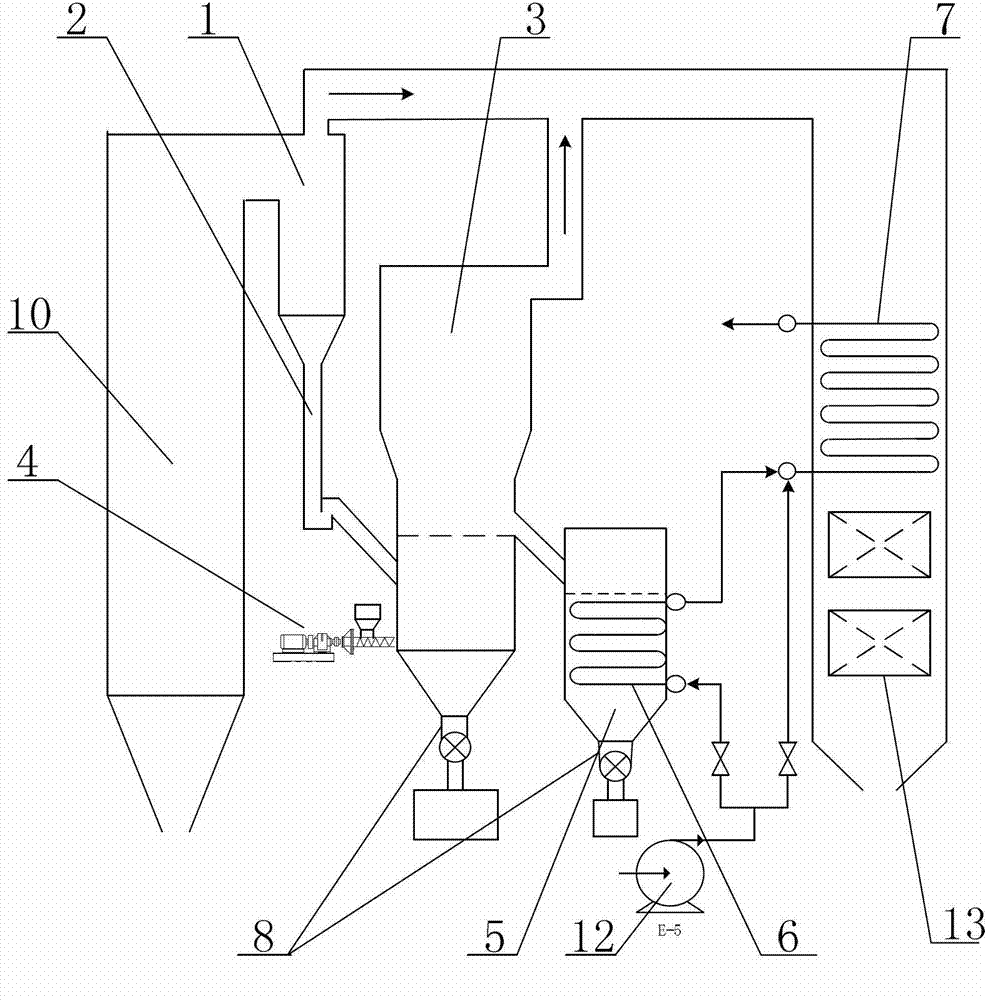
[0029] Example 1: figure 1 It is a structural schematic diagram of the fly ash treatment device of the bubbling fluidized bed incinerator according to the present invention.

[0030] Such as figure 1 Shown: Fly ash treatment device for a bubbling fluidized bed incinerator (garbage incineration) in a factory, including cyclone separator 1 (high-temperature and high-efficiency cyclone separator), fly ash conveying system 2, and bubbling fluidized bed device 3 and moving bed ash cooler 5, the cyclone separator 1 is arranged between the bubbling fluidized bed incinerator 10 and the tail flue, specifically: the cyclone separator 1 is arranged in the bubbling fluidized bed The furnace outlet of the incinerator 10, in addition, the cyclone separator 1 communicates with the bubbling fluidized bed device 3 through the fly ash conveying system 2 at the same time, and the moving bed ash cooler 5 is set in the bubbling flow The overflow port on the side of the fluidized bed device 3 com...

Embodiment 2

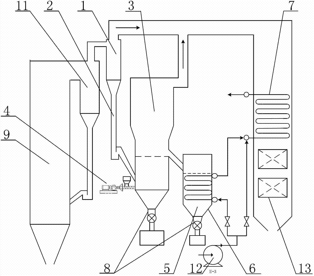
[0036] Example 2: figure 2 It is a structural schematic diagram of the fly ash treatment device of the circulating fluidized bed incinerator according to the present invention.

[0037] like figure 2 As shown: the structure of the fly ash treatment device for a 75t / h circulating fluidized bed incinerator 9 in a certain power plant is basically the same as the fly ash treatment device for a bubbling fluidized bed incinerator 10, the difference is that when the flow When the fluidized bed incinerator is a circulating fluidized bed incinerator 9, the cyclone separator 1 is arranged at the outlet of the cyclone separator 11 of the circulating fluidized bed incinerator. Since the other structures are completely identical, no further details are given.

[0038] In addition, the fly ash treatment process of the circulating fluidized bed incinerator 9 described in this embodiment is basically the same as the fly ash treatment process of the bubbling fluidized bed incinerator 10 de...


PUM

PropertyMeasurementUnit
Diameteraaaaaaaaaa

Abstract

The invention relates to a flying ash processing device of a fluidized bed incinerator. The flying ash processing device comprise a cyclone separator, a flying ash conveying system, a bubble fluidized bed device and a moving bed ash cooler; the cyclone separator is arranged between the fluidized bed incinerator and a tail part flue and is communicated with the bubble fluidized bed device through the flying ash conveying system at the same time; the moving bed ash cooler is communicated with the bubble fluidized bed device; a buried tube heat exchanger is further arranged inside the moving bed ash cooler; the input end of the buried tube heat exchanger is connected with a water feeding pump of the fluidized bed incinerator; and the output end of the buried tube heat exchanger is connected with a coal economizer of the fluidized bed incinerator. With the adoption of the flying ash processing device, the flying ash is effectively captured before the pollutants are accumulated to the surface of the flying ash, and the sensible heat of the flying ash is effectively absorbed, so that the discharge quantity and the processing cost of the flying ash are greatly reduced, the accumulated ash, the abrasion and the corrosion to the heated plane at the tail part of the fluidized bed incinerator are reduced, the resource utilization of the flying ash is realized, the defects that a traditional method is large in capacity-increase and high cost are made up, the sensible heat of the flying ash is effectively used, and the heat economy of the system is improved.

Description

technical field [0001] The invention relates to a treatment device for sludge and fly ash of a fluidized bed incinerator for garbage, and belongs to the technical field of solid waste incineration. Background technique [0002] With the rapid development of the economy, the acceleration of urbanization and the continuous improvement of people's living standards, the generation of urban garbage and sludge in my country is increasing at a rate of 8% to 10% or even more than 10% per year. How to deal with urban sludge and garbage reasonably and effectively has become an environmental protection problem to be solved urgently. At present, municipal sludge is mainly disposed of in three ways: landfill, composting and incineration, while urban waste is mainly disposed of in two ways: landfill and incineration. Among them, the incineration method can reduce the volume of sludge and garbage by 90%, and reduce the volume by 75%. Compared with other treatment methods, it can better ac...

Claims


Application Information

Patent Timeline
IPC IPC(8): F23G5/30F23G5/44
Inventor 陈晓平马吉亮杨叙军杨汉文赵长遂刘道银梁财姜中孝毛军华林敏
Owner WUXI GUOLIAN ENVIRONMENTAL SCI & TECH
Why Eureka
Try Eureka