Metal foil for negative electrode collector

A technology of negative electrode current collector and metal foil, which is applied in the field of metal foil for new negative electrode current collector, can solve the problems of strength decrease, current collector strength decrease, etc., and achieve the effect of low resistance value

Inactive Publication Date: 2013-01-30
TOYO ALUMINIUM KK
View PDF10 Cites 26 Cited by
  • Summary
  • Abstract
  • Description
  • Claims
  • Application Information

AI Technical Summary

Problems solved by technology

However, providing through-holes will reduce the strength of the current collector, and the problem of strength reduction will be more serious if the hole diameter is larger as described above.

Method used


Image

  • Metal foil for negative electrode collector
  • Metal foil for negative electrode collector
  • Metal foil for negative electrode collector

Examples


Embodiment 1

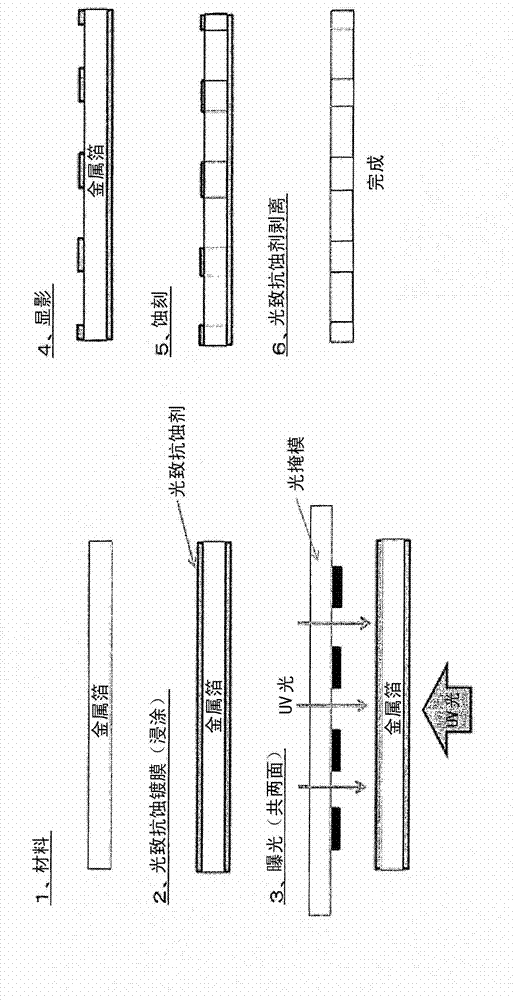
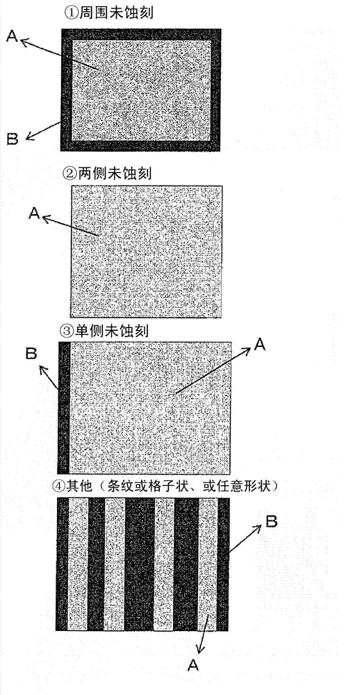
[0078] Electrodeposited copper foil, which is a coil-shaped winding product with a thickness of 10 μm, a width of 300 mm, and a length of 250 m, is dip-coated via a negative-type acrylic resin photoresist solution, and coated on both sides. After 5 μm, drying was performed at 80°C. by optical mapper as depicted by the Figure 4 Photomask of the pattern shown, irradiated at 100mj / cm on one side 2 Ultraviolet rays, on the other side, irradiate the above-mentioned ultraviolet rays on the entire surface under a matte mask. As a developing step, in order to dissolve the photoresist in the photomask portion, the photoresist was removed by dipping in a carbonated soda solution. The obtained material was immersed in copper chloride at a liquid temperature of 50° C. to etch the metal foil. The immersion time at this time was 30 seconds. After performing etching, the photoresist layer was stripped by dipping in a sodium carbonate (NaOH) solution. Then, antirust treatment, washing, ...


PUM


Abstract

Disclosed is a metal foil for a negative electrode collector, said metal foil achieving a low resistance value. The metal foil for a negative electrode collector has a plurality of through holes that reach the foil rear surface from the foil front surface, and the metal foil has a region having a through hole density of 1,000 holes / cm2 or more.

Description

technical field [0001] The invention relates to a metal foil for a new negative electrode current collector. More specifically, it relates to a through foil for negative electrode current collectors used as current collectors of lithium ion batteries, lithium ion capacitors, electric double layer capacitors, and the like. Background technique [0002] For example, aluminum, stainless steel, etc. are used as positive electrode current collectors of lithium ion batteries, lithium ion capacitors, electric double layer capacitors, etc.; stainless steel, copper, nickel, etc. are used as negative electrode current collectors. [0003] However, a higher voltage is required to increase the energy density of lithium-ion batteries, lithium-ion capacitors, electric double layer capacitors, etc. In order to increase the energy density, it is preferable to use predoping (predope) technology to reduce the potential of the negative electrode. Therefore, in order to perform pre-doping eff...

Claims


Application Information

Patent Timeline
Patent Type & Authority Applications(China)
IPC IPC(8): H01M4/70H01M4/66C23F1/02H01G11/68H01G11/70H01G11/06H01G11/66
CPCY02E60/12H01M4/661H01M4/70G03F7/2032G03F7/0015C23F1/02C23F1/14H01G9/016Y02E60/13H01G11/06H01M4/742H01G11/70H01G11/68Y02E60/10H01G11/74
Inventor 目秦将志小西敦志村松贤治
Owner TOYO ALUMINIUM KK
Why Eureka
Try Eureka