Reduction furnace with inner heating containers for producing direct induction iron
A technology of reducing iron and reducing furnace, which is applied in the field of heating liner reducing furnace for direct reduction iron production, can solve the problems of backward equipment level, high product cost, poor sales, etc., and achieves prevention of excessive heating temperature and excellent environmental protection performance. , the effect of reducing production costs
- Summary
- Abstract
- Description
- Claims
- Application Information
AI Technical Summary
Problems solved by technology
Method used
Image

Examples
Embodiment Construction
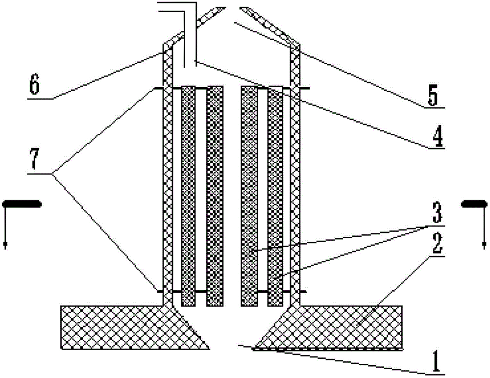
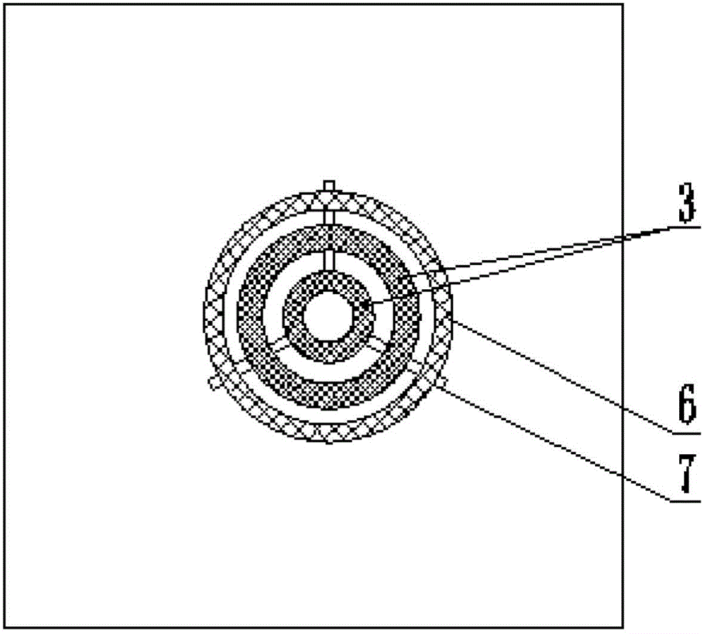
[0019] Embodiments of the invention. Heating liner reduction furnace for direct reduced iron production, such as figure 1 and 2 As shown, the structure includes a furnace body, the outer wall of the furnace body is a refractory insulation layer 6, and a heating liner 3 is installed in the refractory insulation layer 6. The heating liner 3 is connected with a conductive device 7, and the top of the furnace body is installed with a feed inlet 5. A discharge port 1 is installed at the bottom of the body of furnace. Such as figure 2 As shown, the heating liner 3 can be in a circular structure, which is convenient for manufacture and installation. In order to improve heating efficiency and capacity, more than one heating inner tank 3 can be used in the furnace body, and heating channels are formed between the heating inner tanks 3 and between the heating inner tanks 3 and the inner wall of the furnace.
[0020] The heating liner 3 can adopt existing electric heating elements s...
PUM
 Abstract
Description
Claims
Application Information
PatSnap Eureka turns technology decisions into work you can execute. Powered by our Innovation Knowledge Graph, it runs expert workflows across engineering, life sciences, materials and intellectual property. Get your review-ready output in minutes.


