Air-cooled heat pump circulating system and heating and refrigerating methods thereof

A technology of circulation system and air-cooled heat pump, which is applied in the field of air-cooled heat pump circulation system and refrigeration system heat exchanger, can solve the problems of small heat transfer temperature difference and reduced heat transfer efficiency.

Inactive Publication Date: 2013-02-06
WUXI VOCATIONAL & TECHN COLLEGE
View PDF8 Cites 19 Cited by
  • Summary
  • Abstract
  • Description
  • Claims
  • Application Information

AI Technical Summary

Problems solved by technology

The evaporator designed according to the optimized heat transfer efficiency of the evaporator is mainly to reduce the evaporation pressure drop as much as possible on the basis of appropriately increasing the heat transfer coefficient of the evaporating surface on the refrigerant side. Usually, it is necessary to design a shorter single-circuit heat exchange tube length and improve the circuit temperature. Quantity, in order to keep the mass flow rate of the refrigerant in the tube lower than that of the condenser, because the evaporating surface heat transfer coefficient on the refrigerant side increases with the mass flow rate much smaller than the evaporation pressure drop gradient on the refrigerant side increases with the mass flow rate The increase of the heat transfer coefficient of the evaporation surface is conducive to improving the heat transfer efficiency of the heat exchanger, but the evaporation pressure drop has a side effect. In addition, the slope of the refrigerant gas saturation pressure curve under low pressure is high, and the evaporation pressure drop The larger the value is, the smaller the heat transfer temperature difference in the evaporation process is, and the heat transfer efficiency decreases rapidly.

Method used


Image

  • Air-cooled heat pump circulating system and heating and refrigerating methods thereof
  • Air-cooled heat pump circulating system and heating and refrigerating methods thereof
  • Air-cooled heat pump circulating system and heating and refrigerating methods thereof

Examples


Embodiment Construction

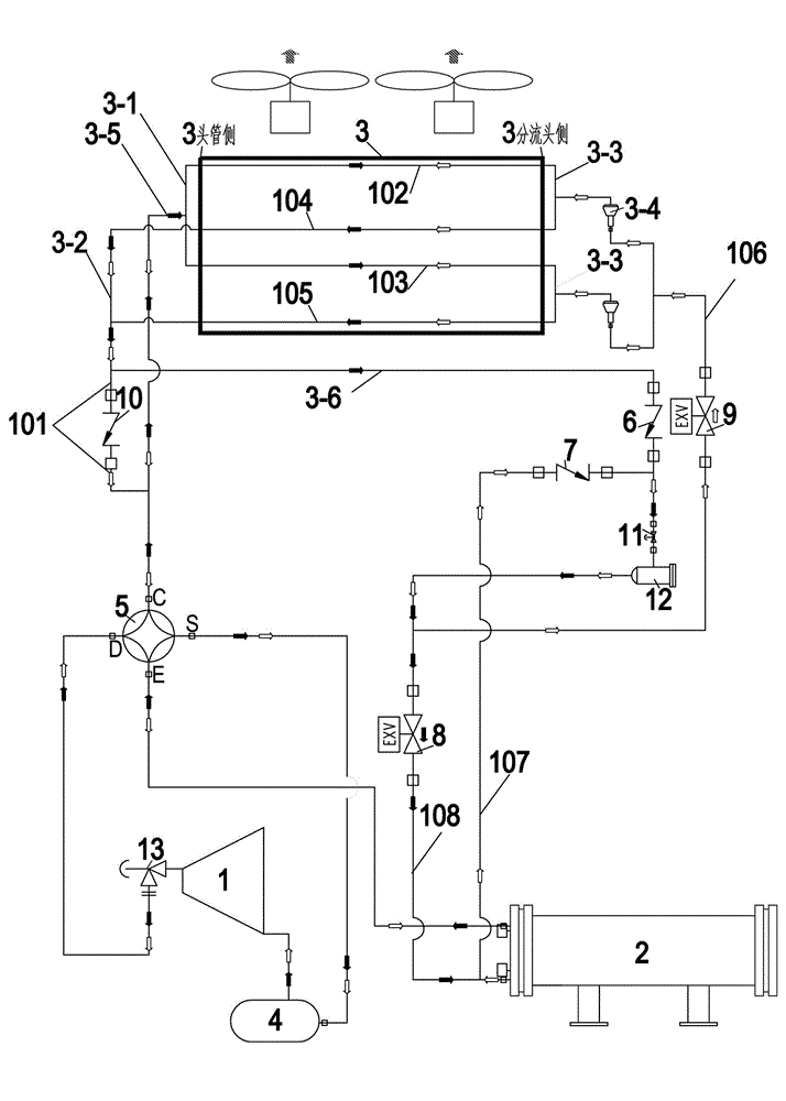
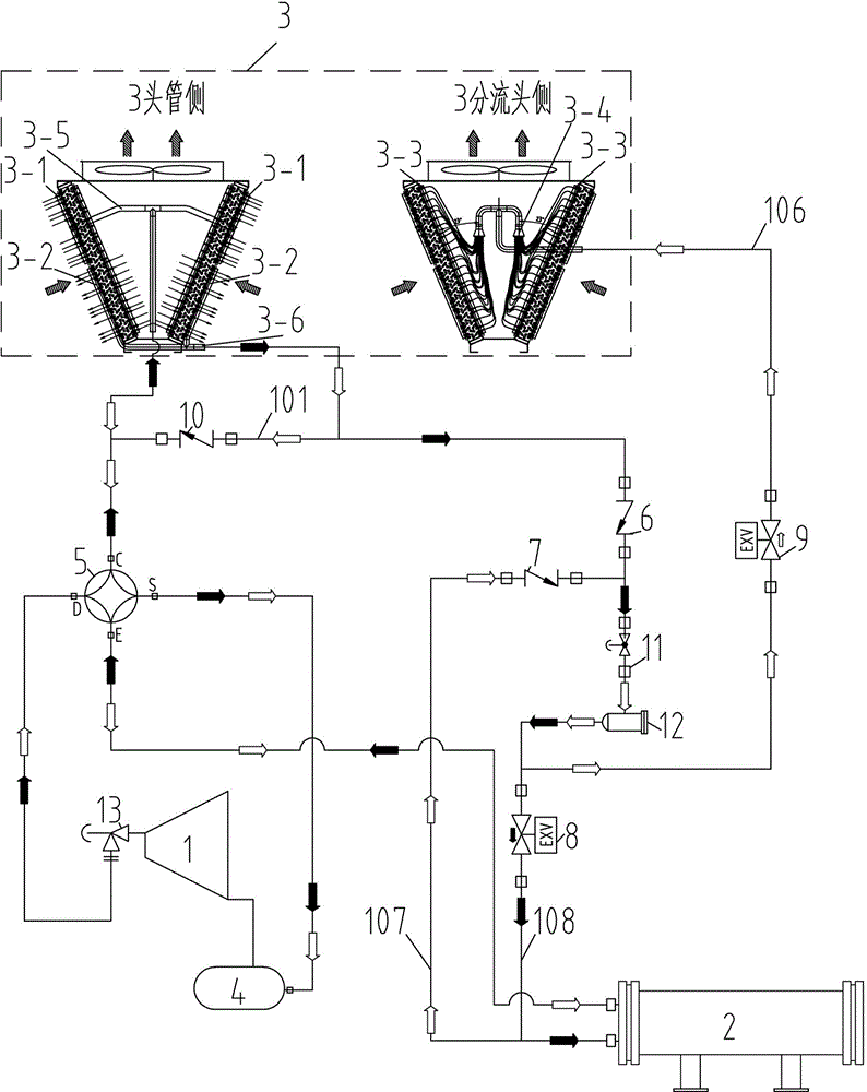
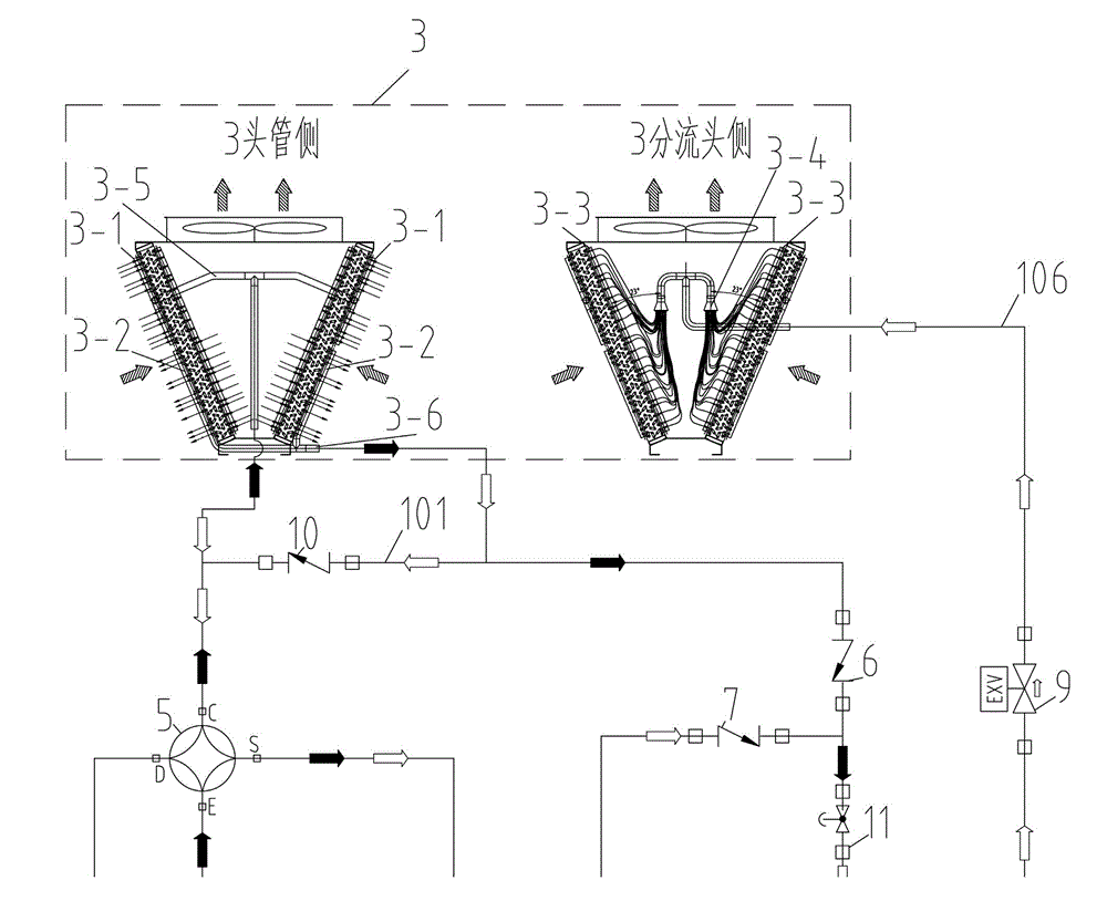
[0043] Refer to attached Figure 1~3 , an air-cooled heat pump circulation system includes a shell-and-tube heat exchanger 2, an air-cooled fin-tube heat exchanger 3, a compressor 1, a gas-liquid separator 4, a four-way reversing valve 5, a refrigeration check valve 6, Heating check valve 7, cooling expansion valve 8, heating expansion valve 9, heating suction check valve 10, exhaust angle valve 13, liquid stop valve 11 and liquid dry filter 12;

[0044] The air-cooled finned tube heat exchanger 3 has a condenser air header / evaporator return air header 3-1, a condenser liquid header / evaporator return air header 3-2, and a condenser secondary distribution set. Liquid pipe / evaporator liquid header 3-3, split head and split pipe 3-4, condenser exhaust head pipe / evaporator return head pipe 3-5 and condenser liquid phase pipe 3-6.

[0045] The exhaust port of the compressor 1 is connected to the air-cooled finned tube heat exchanger 3 through the exhaust angle valve 13, the D port...


PUM


Abstract

The invention provides an air-cooled heat pump circulating system and relates to heat exchangers of refrigeration systems. Air-cooled finned tube heat exchangers serve as the air-cooled heat pump circulating systems of both a condenser and an evaporator. The air-cooled heat pump circulating system comprises a shell-and-tube heat exchanger, an air-cooled finned tube heat exchanger, a compressor, a gas-liquid separator, a four-way reversing valve, a refrigeration non-return valve, a heating non-return valve, a refrigeration expansion valve, a heating expansion valve, a heating inspiration non-return valve, an exhaust corner valve, a liquid path stop valve and a liquid path drying filter, wherein the air-cooled finned tube heat exchanger is provided with a condenser gas header / evaporator gas return header, a condenser collector tube / evaporator gas return header, a condenser secondary distribution collector tube / evaporator liquid distribution header, a shunt head and shunt tube, a condenser exhaust head tube / evaporator gas return head tube and a condenser liquid phase tube. The air-cooled heat pump circulating system comprises two circulation processes of heating and refrigeration. In the two processes, the air-cooled finned tube heat exchanger has different single-circuit heat exchange tube lengths, circuit quantities and in-tube refrigerant mass velocities, and meanwhile, the heat transmission efficiency is optimized.

Description

technical field [0001] The invention relates to an air-cooled heat pump circulation system, which relates to a refrigeration system heat exchanger, in particular to an air-cooled heat pump circulation system using an air-cooled finned tube heat exchanger as a condenser and an evaporator. Background technique [0002] The principle of the known refrigeration system is: the refrigeration system works in a high-temperature environment and a low-temperature environment. In the refrigeration cycle system, the refrigerant circulation will discharge the heat in the low-temperature environment to the high-temperature environment. In the heat pump cycle system, the refrigerant circulation will The low-grade heat in the low-temperature environment is converted into high-grade heat together with the input power and discharged to the high-temperature environment. [0003] In the existing air-cooled heat pump cycle system, in the air-cooled heat pump unit, when the refrigeration cycle is...

Claims


Application Information

Patent Timeline
Patent Type & Authority Applications(China)
IPC IPC(8): F25B13/00F25B39/00F25B41/04
Inventor 商萍君王明星陈利军吴华萍陈武
Owner WUXI VOCATIONAL & TECHN COLLEGE
Why Eureka
Try Eureka