Direct-cooling freezing wind tunnel realization method and direct-cooling freezing wind tunnel realization system
A realization method and wind tunnel technology, applied in the field of aerodynamic experiments, can solve the problems of high construction and operation costs, high fan driving power, and increased flow resistance of icing wind tunnels, so as to reduce disturbance and loss, reduce construction and Operating cost, effect of simplified structure
- Summary
- Abstract
- Description
- Claims
- Application Information
AI Technical Summary
Problems solved by technology
Method used
Image
Examples
Embodiment 1
[0038] Embodiment 1. Small-scale straight-through icing wind tunnel
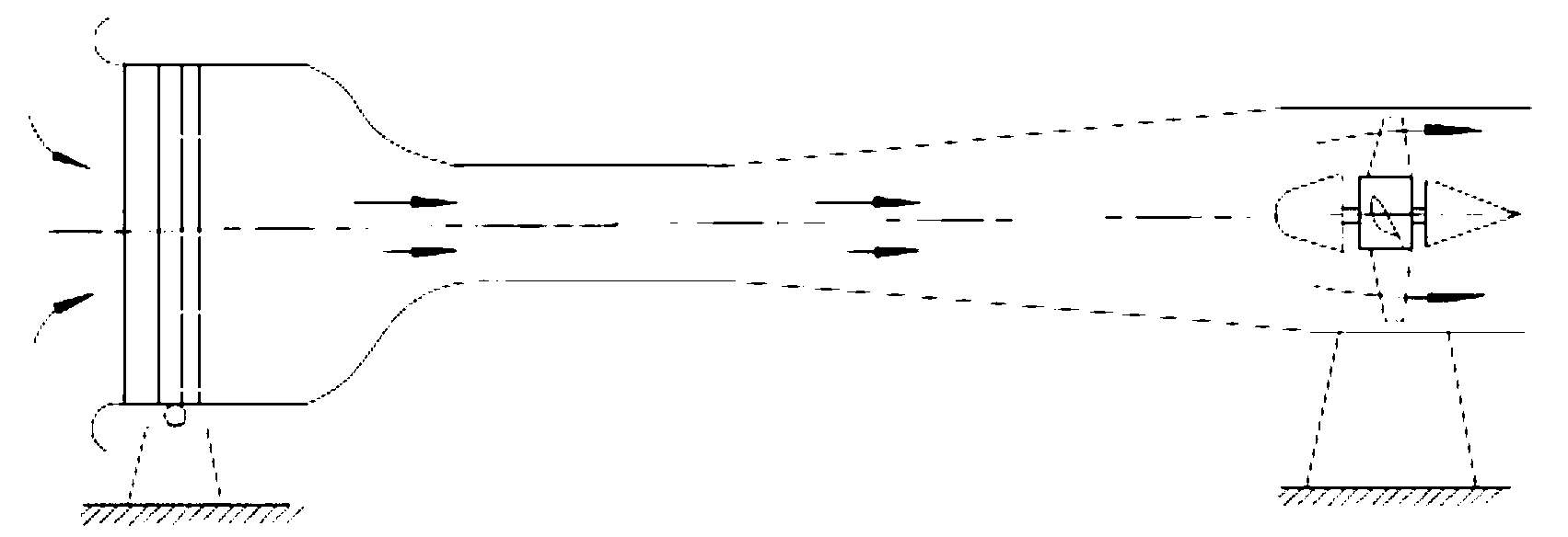
[0039] For a small DC wind tunnel, it is assumed that the size of the wind tunnel test section is 0.15x0.15x0.30m, the incoming flow velocity of the wind tunnel is 8m / s, and the flow rate is 0.18m 3 / s, the temperature is 5°C, and the airflow temperature required for the test is -5°C. In this example, low-temperature nitrogen is used as the low-temperature gas. After the low-temperature nitrogen gas is output from the liquid nitrogen tank and vaporized, the temperature rises from -196°C to -193°C due to the loss of cooling capacity of the pipeline. At the same time, it is assumed that the speed of the low-temperature nitrogen entering the wind tunnel from the spray system is the same as the test air flow, then The flow rate of low-temperature nitrogen gas that needs to be introduced is about 0.01m 3 / s, accounting for only about 1 / 18 of the total air flow in the test.
[0040] According to the position of...
Embodiment 2
[0042] Example 2. Small reflux icing wind tunnel
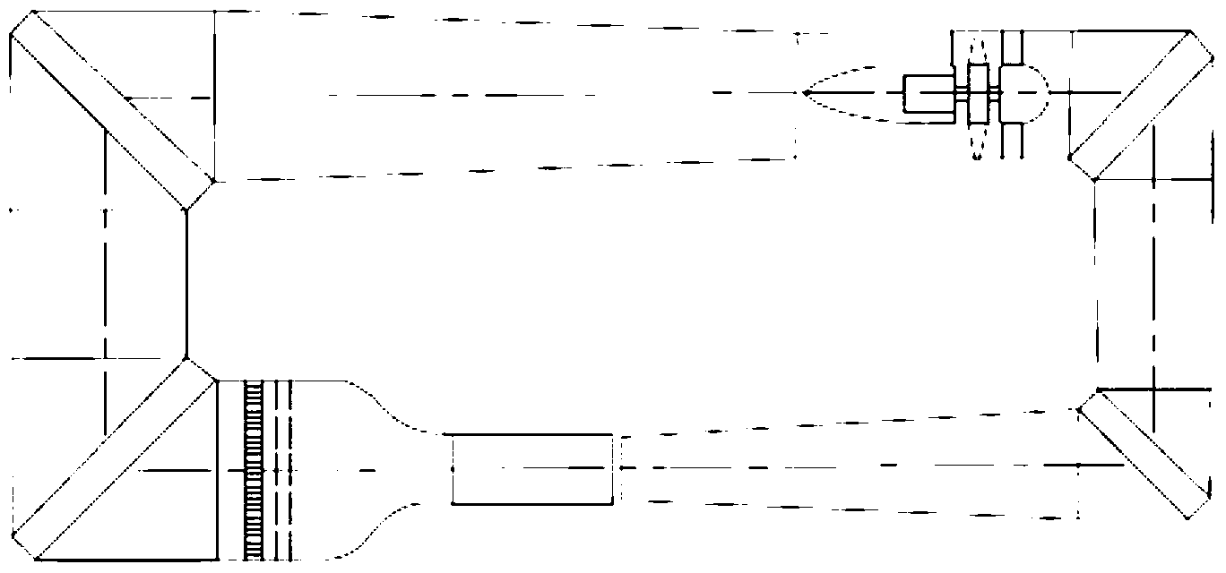
[0043] Assume that the size of the test section of the small-scale recirculation icing wind tunnel described in this example is the same as that of the straight-through wind tunnel in Case 1, that is, 0.15x0.15x0.30m, and that the test air velocity is the same, that is, the same is 8m / s, and the flow rate 0.18m 3 / s, the temperature is 5°C, and the airflow temperature required for the test is -5°C, since the low-temperature airflow in the recirculation wind tunnel can be reused, that is to say, the cold injected into the test airflow will be reused, so in After the test air flow is reduced, the cooling capacity added each time is only the cooling capacity lost due to the heat loss of the equipment, so it can be expected that in the return type wind tunnel, the flow rate of low-temperature gas that needs to be used is smaller, that is, less than 0.01m 3 / s.
[0044] In terms of structural design, the low-temperature gas spray...
Embodiment 3
[0045] Example 3. Large-scale recirculation icing wind tunnel
[0046] Taking the geometry and test parameters of the large-scale icing wind tunnel at the Glenn Center in the United States as a reference, it is assumed that the size of the test section is 2.7x1.8x6m, the maximum wind speed is 179m / s, and the minimum temperature is -40°C. experimenting. Assume that the indoor temperature during the test is 10°C, the test wind speed is 100m / s, and the test temperature is -25°C. After the test airflow is stable, it is assumed that there is 2% of the cooling leakage, and the flow rate of the test airflow is 486m 3 / s. The cooling capacity required at start-up is about 21000J / s, and the nitrogen flow rate for cooling is 100m 3 / s, the nitrogen flow required after stabilization is 2m 3 / s. The total length of the wind tunnel is about 70 meters. Assuming that it takes 1 second to complete the cooling process at startup (that is, the cold air runs around the wind tunnel), 150 lite...
PUM
 Abstract
Description
Claims
Application Information
 - R&D
- Intellectual Property
- Life Sciences
- Materials
- Tech Scout
- Unparalleled Data Quality
- Higher Quality Content
- 60% Fewer Hallucinations
Browse by: Latest US Patents, China's latest patents, Technical Efficacy Thesaurus, Application Domain, Technology Topic, Popular Technical Reports.
© 2025 PatSnap. All rights reserved.Legal|Privacy policy|Modern Slavery Act Transparency Statement|Sitemap|About US| Contact US: help@patsnap.com


