Method and device for controlling NOx concentration in smoke gas of cement kiln

A technology of control device and central controller, applied in separation methods, chemical instruments and methods, and separation of dispersed particles, can solve problems affecting the long-term stable operation of cement kiln production lines, threats to normal operation of induced draft fans, and blockage of catalyst pores, etc., to achieve Reduced denitrification costs, reduced tail ammonia escape, and strong adaptability to load fluctuations

Active Publication Date: 2013-02-13
ENVIRONMENTAL SCI RES & DESIGN INST OF ZHEJIANG PROVINCE
View PDF5 Cites 23 Cited by
  • Summary
  • Abstract
  • Description
  • Claims
  • Application Information

AI Technical Summary

Problems solved by technology

Due to the cement kiln dust content as high as 80 ~ 100g / Nm 3 , it is easy to cause catalyst pore blockage, so that the pressure drop of the system increases rapidly, which poses a serious threat to the normal operation of the induced draft fan, thus affecting the long-term stable operation of the cement kiln production line; at the same time, sodium, potassium and other water-soluble alkali metal compounds in the cement kiln flue gas Catalyst V 2 o 5 The reaction leads to poisoning of the catalyst, reducing its activity; in addition, the high concentration of CaO in the flue gas, and the SO oxidized by the catalyst 3 Generate CaSO 4 , covering the catalyst surface and reducing its activity

Method used


Image

  • Method and device for controlling NOx concentration in smoke gas of cement kiln
  • Method and device for controlling NOx concentration in smoke gas of cement kiln

Examples


Embodiment 1

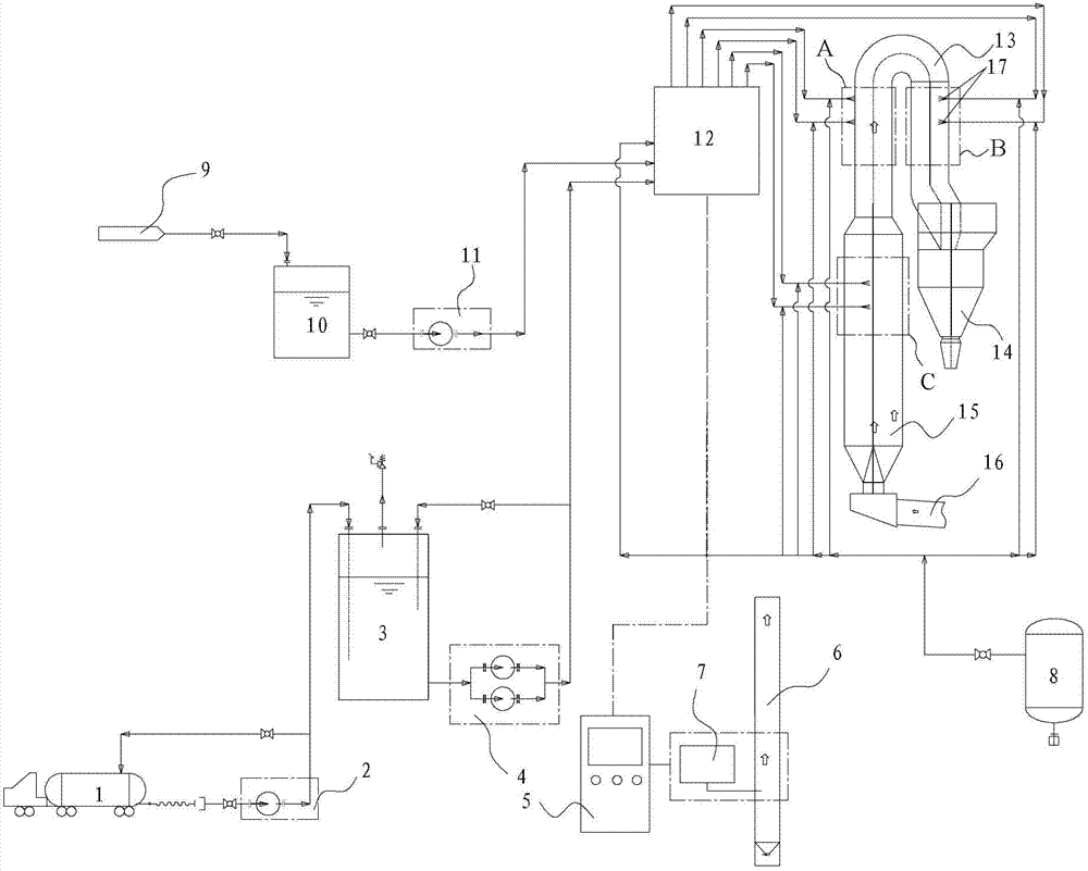
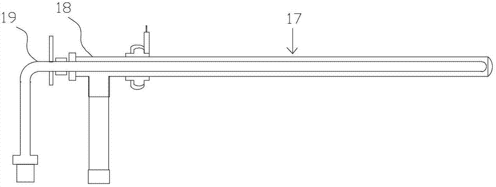
[0046] The spray gun is installed on the outlet flue ( figure 1 Injection module 1 shown in the dotted box in A). According to the CFD simulation results, the injection points are divided into three layers, each layer has 2 nozzles, and they are distributed on the circular flue. All injection points fall within the temperature range of 800-950°C. There are spray guns installed at the three layers of the system, and each spray gun is numbered A1, A2, B1, B2, C1, C2, and the system is put into automatic operation. X Concentration, flow and other parameter feedback (temperature changes, the system selects the appropriate temperature window according to the temperature parameter feedback, that is, changes the injection point level; flow changes, what needs to be changed is the size of the ammonia injection amount of the system, and the change of NSR mainly depends on the NOx concentration Change and change), the system automatically selects the point, A1, A2, B1, B2, C1, C2 can ...

Embodiment 2

[0053] According to the CFD simulation results, the spray gun is installed in the upper part of the decomposition kiln body ( figure 1 Injection module 3) and outlet flue ( figure 1 Injection module 2 shown in the dotted line box in middle B), the injection points are divided into two layers, each layer has 3 pieces (A1, A2, A3, B1, B2, B3). All injection points fall within the temperature range of 800-950°C. According to the temperature, concentration, flow and other parameter feedback of the system, the system automatically selects the point, and 3-6 spray guns can be selected from A1, A2, A3, B1, B2, B3, which are the spray gun points actually put into operation.

[0054] The flue gas treatment capacity of the denitrification system is 3.0×10 5 N m 3 / h, NOx content 700mg / Nm 3 , adjust NSR=1.8, kiln tail chimney NO X The concentration is reduced to about 150mg / Nm 3 , the denitrification rate fluctuates around 78%.

[0055] Adjust NSR=1.7, kiln tail chimney NO X The ...

Embodiment 3

[0060] According to the CFD simulation results, it is determined that the outlet flue is vertically upward on the flue gas pipeline ( figure 1 Injection module 2 shown in the dotted line box in middle A), the injection point is a layer, with a total of 8 spray guns (A1, A2, A3, A4, A5, A6, A7, A8). All injection points fall within the temperature range of 800-950°C. The spraying points of the system are all equipped with spray guns, and the system is put into automatic operation. According to the feedback of parameters such as system temperature, concentration, and flow rate, the system automatically selects the point. A1, A2, A3, A4, A5, A6, A7, and A8 can be selected Select 4-8 spray guns as the actual spray gun points that are put into operation.

[0061] The system automatically selects the point as the spray gun point actually put into operation.

[0062] The flue gas treatment capacity of the denitrification system is 6.0×10 5 N m 3 / h, NOx content 1000mg / Nm 3 , adj...


PUM


Abstract

The invention discloses a method and device for controlling NOx concentration in smoke gas of a cement kiln; the device comprises a decomposing kiln, a preheater and a reducing agent supply device, wherein the bottom of the decomposing kiln is communicated with a kiln tail chimney of the cement kiln by an inlet smoke flue; the top of the decomposing kiln is communicated with the preheater by an outlet smoke flue; a plurality of spray guns communicated with the reducing agent supply devices are arranged at or/or in the middle upper part of the decomposing kiln or/and the outlet smoke flue in a layered way; and the device further comprises a central controller and a smoke gas automatic monitoring system, wherein the central controller is connected to the reducing agent supply devices; and the smoke gas automatic monitoring system is used for monitoring NOx concentration and smoke gas flow information in the kiln tail chimney and transmitting the NOx concentration and smoke gas flow information to the central controller. According to the invention, as a reducing agent is sprayed into the decomposing kiln through multi-site combined control, high removal rate of the NOx can be achieved without an SNCR (Selective Non Catalytic Reduction) and SCR (Selective Catalytic Reduction) combined technology.

Description

technical field [0001] The invention relates to the technical field of chemical environmental protection, in particular to a NO x Concentration control methods and devices. Background technique [0002] According to the formation mechanism of NOx in the cement industry, the control technologies for NOx are mainly divided into two categories, one is to control the combustion process to reduce the formation of NOx; the other is to take removal measures for the already formed NOx. The control technologies for the combustion process mainly include low NOx burners, fuel staged combustion, air staged combustion and other means to reduce the generation of thermal NOx by controlling the oxygen supply or reducing the flue gas temperature. By monitoring the combustion process, such as the excess air ratio and flue gas temperature of the rotary kiln, and the concentration of pollutants such as NOx and CO at the chimney outlet, the combustion is optimized. Under the premise of meeting...

Claims


Application Information

Patent Timeline
Patent Type & Authority Applications(China)
IPC IPC(8): B01D53/79B01D53/56
Inventor 顾震宇韦彦斐金瑞奔朱虹范海燕周荣陆建海汪昊其
Owner ENVIRONMENTAL SCI RES & DESIGN INST OF ZHEJIANG PROVINCE
Why Eureka
Try Eureka