Thermal treatment method of cam shaft

A heat treatment method and camshaft technology, applied in heat treatment furnaces, heat treatment equipment, process efficiency improvement, etc., can solve the problems of uneven quenching hardness, uneven depth of hardened layer, inconsistent heat transfer speed, increased production cost, etc., and achieve fatigue strength And the service life is improved, the depth of the hardened layer is uniform and reasonable, and the metallographic structure is uniform and reasonable.

Active Publication Date: 2013-02-13
CHONGQING YUEJIN MACHINERY
View PDF5 Cites 12 Cited by
  • Summary
  • Abstract
  • Description
  • Claims
  • Application Information

AI Technical Summary

Problems solved by technology

However, except for the base circle, the shape and size of the cam profile change, and the radius of curvature is different at each place. According to the characteristics of the induced current, the current density distributed in the axial and circumferential directions of the profile is not uniform. Yes, the sharp corner effect at the edge is more obvious, and the heat transfer rate at each place is also inconsistent, resulting in faster heating rate and faster heat transfer rate at the edge of the base circle, while the heat transfer rate at the edge of the lift is faster than that of the base circle. The circle is slow, but the heating rate is faster than the base circle, which causes a large difference in temperature and temperature gradient between the base circle and the lift of the cam, making the quenching hardness and hardened layer depth very uneven, which cannot meet the design requirements , and the metallographic structure is often out of tolerance, and sometimes quenching cracks appear, which will directly cause the wear resistance, fatigue strength and service life of the product to fail to meet the design requirements, and the product scrap rate is high, which significantly increases the production cost

Method used


Image

  • Thermal treatment method of cam shaft

Examples


Embodiment 1

[0020] (1) Ultrasonic frequency induction heating and quenching

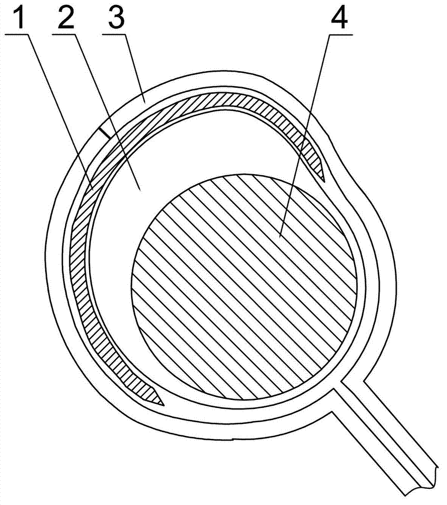
[0021] Install the camshaft 4 on the quenching machine tool, set the induction coil 3 of the super-audio frequency induction heating device on the outside of the cam 2, and place a shielding plate 1 (material Q235 steel) between the cam lift part and the induction coil 3, Use the above-mentioned supersonic frequency as the heating power supply, and then perform the heating and quenching operation in the following order:

[0022] a. Preheating, under the conditions of voltage 360V and current 175A, preheat for 35s;

[0023] b. Stop heating after the preheating is completed, then remove the shielding plate 1, stop heating for 6 seconds, and continue heating for 9 seconds under the conditions of voltage 415V and current 210A;

[0024] c. Cooling, using polyvinyl alcohol aqueous solution with a mass concentration of 1.2% as the quenching medium, the injection pressure is gradually reduced from 0.15Mpa to 0.05Mpa, c...

Embodiment 2

[0029] (1) Ultrasonic frequency induction heating and quenching

[0030] Camshaft 4 will be installed on the quenching lathe according to embodiment 1, then carry out heating and quenching operation in the following order:

[0031] a. Preheating, under the conditions of voltage 460V and current 220A, preheat for 42s;

[0032] b. Stop heating after the preheating is completed, then remove the shielding plate 1, stop heating for 7 seconds, and continue heating for 12 seconds under the conditions of voltage 480V and current 235A;

[0033] c. Cooling, using polyvinyl alcohol aqueous solution with a mass concentration of 1.8% as the quenching medium, the injection pressure is gradually reduced from 0.2Mpa to 0.05Mpa, controlled by a servo hydraulic valve, the spray cooling pressure is continuously adjustable, first fast and then slow, spray The time of quenching medium is 170s.

[0034] (2) Tempering

[0035] Put the quenched camshaft 4 into a hot air circulation furnace whose t...


PUM


Abstract

The invention discloses a thermal treatment method of a cam shaft, which solves the problem of non-uniform heating temperature and temperature gradient on a cam profile. The quenching comprises the following steps of: a, preheating: sheathing an induction coil of an induction heating device outside a cam, placing a shielding plate between a cam lifting part and the induction coil, and preheating for 33-45 seconds under the conditions with voltage of 340-480V and current of 160-230A; b, stopping heating, removing the shielding plate, and 5-8 seconds later, continuously heating for 8-14 seconds under the conditions with voltage of 410-500V and current of 200-250A; and c, cooling: cooling the cam with a quenching medium. Through the invention, the quenching hardness range of the produced cam shaft is reduced by 3.5HRC from that of common surface quenching, the depth range of a hardening layer is reduced by 3.7mm, the metallographic structure is obviously improved, and quenching cracks are avoided; and moreover, the wear resistance and fatigue strength of the cam shaft are obviously improved, and the service life of the cam shaft is obviously prolonged.

Description

technical field [0001] The invention relates to a heat treatment method for a camshaft, in particular to an induction heating and quenching heat treatment method for a camshaft. Background technique [0002] The camshaft is one of the key moving parts of the heart of the diesel engine. During the working process, it bears complex stresses such as extrusion, friction, impact, and bending. In order to ensure the safety and reliability of the diesel engine during use, the cam part of the camshaft can be made to have high enough strength, plasticity and toughness through heat treatment, so that the cam profile has high hardness, wear resistance and fatigue strength, so as to ensure the cam shaft life. [0003] In order to make the medium-speed diesel engine camshaft have the above-mentioned properties, according to the different manufacturing materials, there are two methods can be realized: one method is chemical heat treatment, and the other method is surface induction harden...

Claims


Application Information

Patent Timeline
Patent Type & Authority Applications(China)
IPC IPC(8): C21D9/30C21D1/10
CPCY02P10/25
Inventor 张先智明国建何利平张文华
Owner CHONGQING YUEJIN MACHINERY
Why Eureka
Try Eureka