
System and method for in-situ testing of internal electric charge and electric field distribution of dielectric material

A technology of electric field distribution and dielectric materials, applied in the field of measurement, can solve problems such as charge discharge and measurement errors, and achieve the effect of avoiding errors

Inactive Publication Date: 2013-02-27
NO 510 INST THE FIFTH RES INST OFCHINA AEROSPAE SCI & TECH
View PDF6 Cites 14 Cited by
  • Summary
  • Abstract
  • Description
  • Claims
  • Application Information

AI Technical Summary

Problems solved by technology

[0004] The present invention provides a system and method capable of in-situ testing the internal charge and electric field distribution of satellite dielectric materials, which can solve the problem of charge leakage during the test process after the sample is irradiated by high-energy electrons and then the sample is taken out for charge and electric field distribution. put and measure errors

Method used


Image

  • System and method for in-situ testing of internal electric charge and electric field distribution of dielectric material
  • System and method for in-situ testing of internal electric charge and electric field distribution of dielectric material
  • System and method for in-situ testing of internal electric charge and electric field distribution of dielectric material

Examples


Embodiment Construction

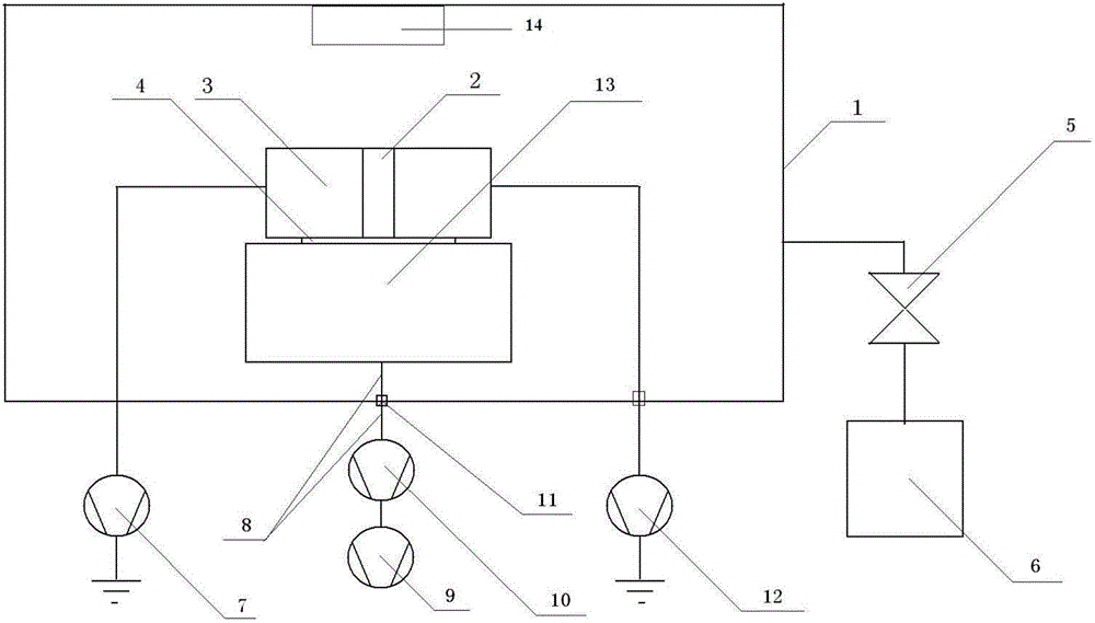
[0037] Such as figure 1 An in-situ test system for the internal charge and electric field distribution of a dielectric material is shown, and the system includes a vacuum tank 1, an upper electrode 3, a solenoid valve 5, a vacuum system 6, a DC high-voltage power supply 7, a test signal line 8, and an industrial computer 9. Oscilloscope 10, shielding flange 11, high-voltage nanosecond pulse generator 12, space charge detection device host 13, and electron accelerator 14.

[0038] Wherein, inside the vacuum tank 1, the host 13 of the space charge detection device is installed on the bottom surface of the vacuum tank 1, the sample 4 is placed on the upper surface of the host 13, and the upper electrode 3 is placed on the sample 4; the upper electrode 3 is a metal cylinder, There is an upper electrode hole 2 along the central axis; the electron accelerator 14 is installed on the top of the vacuum tank 1, and the emission end is directly opposite to the upper electrode hole 2;

...


PUM


Abstract

The invention relates to a system and method for in-situ testing of internal electric charge and electric field distribution of a dielectric material and belongs to the field of measurement. The system comprises a vacuum tank, a top electrode, a solenoid valve, a vacuum-pumping system, a direct-current high-voltage power supply, a testing signal line, an industrial personal computer, an oscilloscope, a shielding flange, a high-voltage nanosecond pulse generator, a space charge detector main machine and an electron accelerator. The method comprises the steps of enabling high-energy electrons to pass through electrode holes to be filled onto the surface of a sample through the electron accelerator, recording tested wave forms through the oscilloscope and the industrial personal computer, and performing data processing to calibrated wave forms recorded by the industrial personal computer and tested wave forms to obtain the electric charge distribution in the sample. The system and the method can perform in-situ monitoring to the internal electric charge and the electric field distribution produced by produced by a space high-energy electron jetting-in space material simulated on the ground. Errors caused by measurement of the sample subjected to irradiation are avoided, and a test signal is not interfered.

Description

technical field [0001] The invention relates to an in-situ test system and method for the internal charge and electric field distribution of a dielectric material, in particular to a system and a method capable of in-situ testing the internal charge and electric field distribution of a star dielectric material, belonging to the field of measurement. Background technique [0002] The electrification in the satellite is generally caused by the injection of high-energy electrons with an energy of 0.1-10 MeV into the material in space. The above-mentioned high-energy electrons can penetrate the satellite structure (satellite surface material, cable sheath, etc.) Charges are deposited on the plates and capacitor components, and when high-energy electrons are injected into the satellite dielectric material, it may lead to a decrease in material strength. If the deposition rate of incident electrons in the medium exceeds its discharge rate, the charge density in the medium will gra...

Claims


Application Information

Patent Timeline
Patent Type & Authority Applications(China)
IPC IPC(8): G01R29/24G01R29/14
Inventor 柳青李得天陈益峰秦晓刚汤道坦王俊史亮孔风连
Owner NO 510 INST THE FIFTH RES INST OFCHINA AEROSPAE SCI & TECH
Learn More