

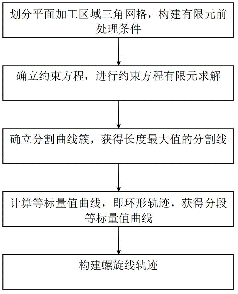
Generation method of planar spiral and annular milling tracks
A plane spiral and trajectory generation technology, applied in the direction of instruments, computer control, simulators, etc., can solve the problems that the cutting trajectory overlap cannot be completely avoided, the lack of offset line distribution optimization (smooth line spacing control, etc., to overcome the helix overlap , uniform row spacing, and the effect of improving processing efficiency
- Summary
- Abstract
- Description
- Claims
- Application Information
AI Technical Summary
Problems solved by technology
Method used
Image

Examples
Embodiment Construction
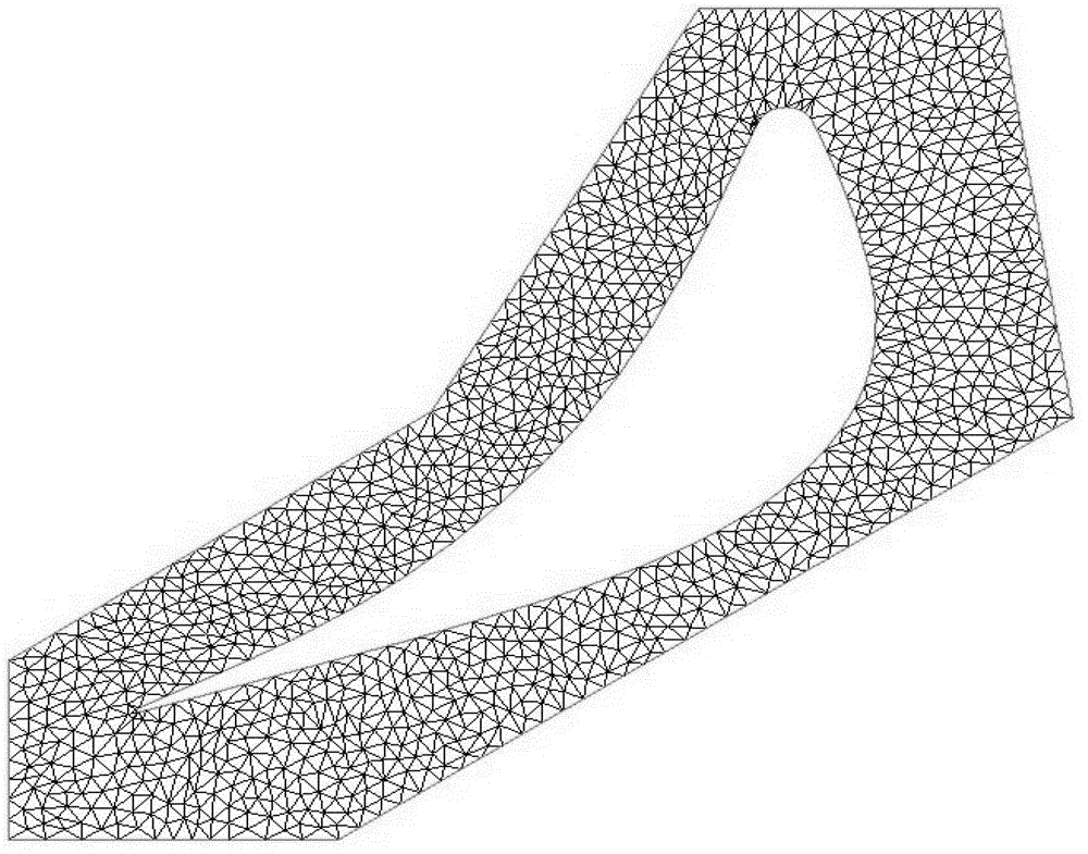
[0044] In order to make the object, technical solution and advantages of the present invention clearer, the present invention will be further described in detail below in conjunction with the accompanying drawings and embodiments. It should be understood that the specific embodiments described here are only used to explain the present invention, not to limit the present invention.
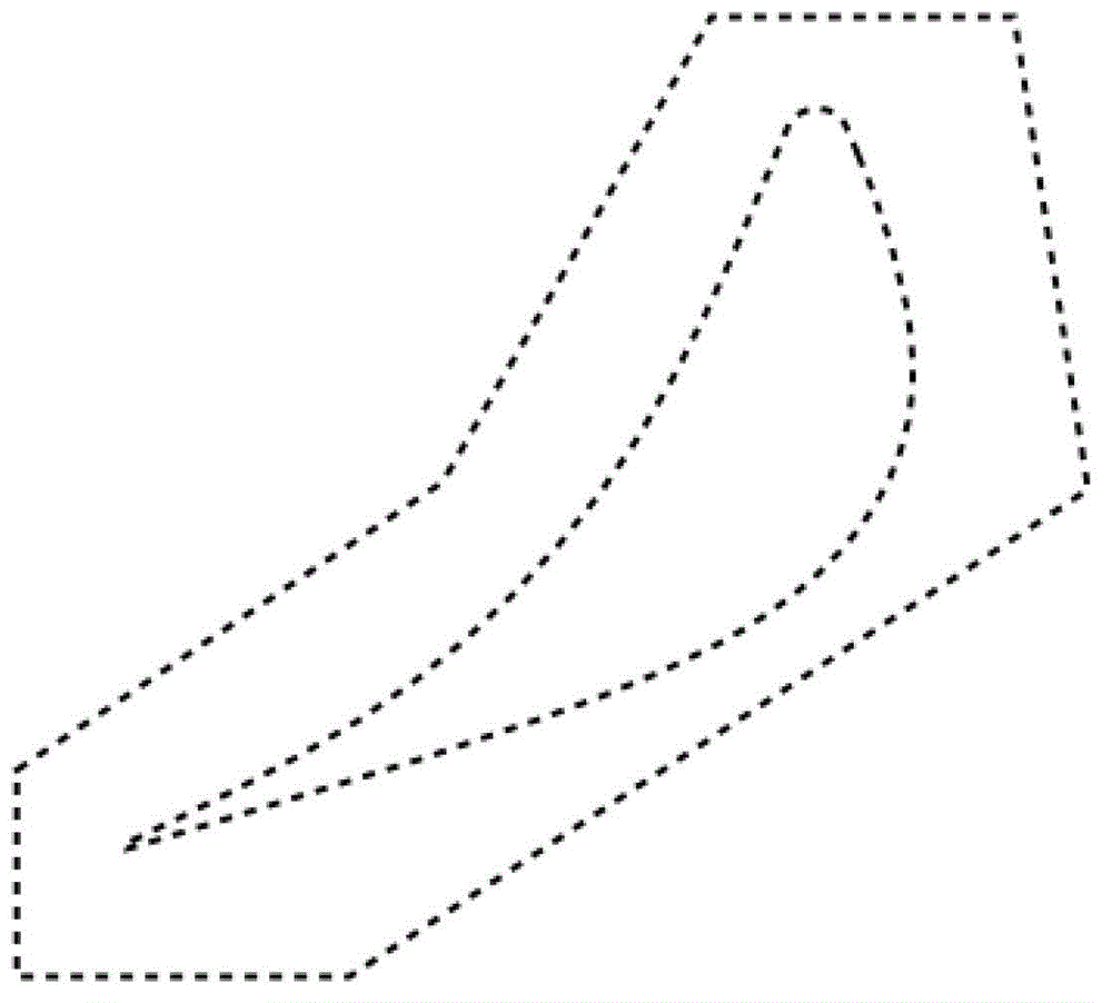
[0045]The present invention will be described in detail below by taking plane cavity spiral milling as an example, but it should be understood that the invention is not limited thereto, and is also applicable to arbitrary boundary blanks (such as square steel roughening of blades, arbitrary polygonal envelope blanks, Machining of part model geometry offset shape blank). In addition, the present invention is also applicable to plane cavity milling, square cavity, triangular aerospace parts, and one or more islands in the cavity.
[0046] Likewise, the implementation of the present invention is not ...
PUM
 Abstract
Description
Claims
Application Information