Tube shell for vacuum package of micro-optical-electronic-mechanic system and manufacture method thereof

A technology of micro-opto-electromechanical system and vacuum packaging, which is applied in the process of producing decorative surface effects, micro-structure devices, and manufacturing micro-structure devices, etc., which can solve the problems of difficult detection, affecting welding air tightness, and low welding efficiency, etc. problem, to avoid damage

Active Publication Date: 2013-03-06
INST OF MICROELECTRONICS CHINESE ACAD OF SCI
View PDF5 Cites 9 Cited by
  • Summary
  • Abstract
  • Description
  • Claims
  • Application Information

AI Technical Summary

Problems solved by technology

By adjusting the welding voltage and welding pressure between the upper and lower electrodes (primary pressure of the cylinder, secondary pressure, etc.) to adjust the welding parameters and optimize the welding quality, but there is a large area of ​​welding efficiency is low, and the welding layer will be densely covered with pinhole-shaped blisters, Thus affecting the airtightness of welding;
[0004] Parallel sealing welding technology belongs to resistance welding. During sealing welding, the electrodes rotate while moving (through the electrode wheel), and the electrodes are intermittently energized under a certain pressure. Contact resistance, the welding current will generate Joule heat at these two contact resistances, making it partially molten between the cover plate and the welding frame, and forming so

Method used


Image

  • Tube shell for vacuum package of micro-optical-electronic-mechanic system and manufacture method thereof

Examples


Embodiment

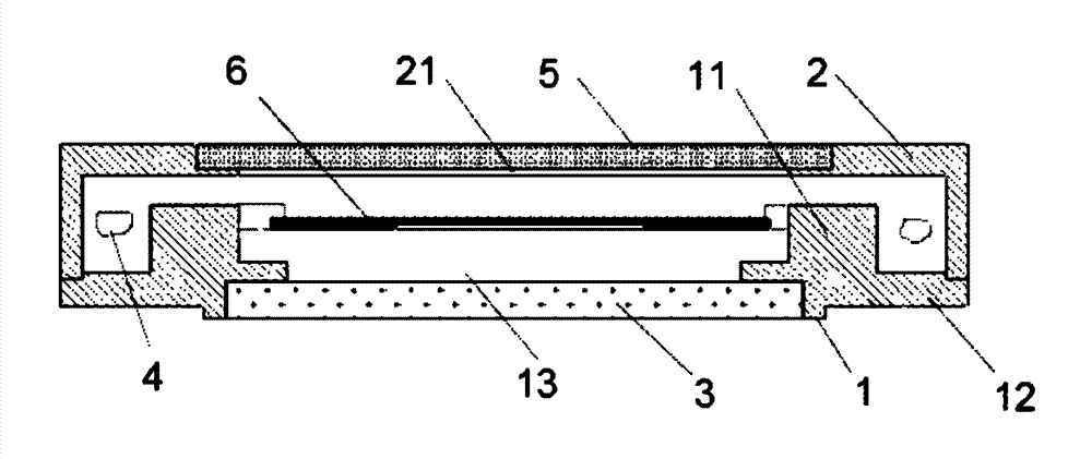
[0031] Embodiment: A tube shell for micro-opto-electromechanical system vacuum packaging, including a base 1, a sealing cap 2, an optical filter 3 and a getter fixing device 4, and a ring is arranged on the inside of one end of the base 1 in a hollow cylindrical structure chip fixing groove, a ring-shaped outer expansion stopper 12 is arranged on the outer wall of the base circumference, the sealing cap 2 covers the outer side of one end of the base 1 and is sealed and fixed with the annular outer expansion stopper 12 on the base, and the other end of the base 1 is provided with There is an opening 13 communicating with the internal space, and the optical filter 3 is sealed and fixedly covered on the outer end surface of the opening 13. The axial end surface of the sealing cap 2 is provided with a light-transmitting window 21 communicating with the interior of the base 1, and a transparent window 21 is also provided. The light sheet 5, the light-transmitting sheet 5 is sealed a...


PUM


Abstract

The invention discloses a tube shell for vacuum package of a micro-optical-electronic-mechanic system and a manufacture method thereof. A chip fixing groove is arranged in a base, a sealing cap is hermetically fixedly connected to an annular externally-extending stopper outside one end of the base, an optical filter hermetically covers an opening of the other end of the base, a light-transmitting plate hermetically fixedly covers the outside of a light-transmitting window on the axial end face of the sealing cap, and a getter fixing device is fixedly arranged in the sealing cap and the base. The manufacture method includes machining the base and the sealing cap, and performing hydrogen burning, decarburization, nickel plating and annealing; machining the getter fixing device, cleaning, blow-drying and baking; performing chromium sputtering to a welding area of the base and the sealing cap, and electrogilding; performing multi-layer welding to the optical filter and the light-transmitting plate by tin-lead solder welding and transition glass respectively, and annealing; adhering the getter fixing device and welding the base with the sealing cap; and performing air leak detection and vacuum pumping. The tube shell is used for vacuum package of the micro-optical-electronic-mechanic system, and chip is protected from failure due to high temperature.

Description

technical field [0001] The invention relates to a tube shell and a manufacturing method thereof, in particular to a tube shell for a micro-opto-electromechanical system and a manufacturing method thereof. Background technique [0002] The traditional electric vacuum packaging process and technology have been developed relatively maturely. Micro-Electronic-Mechanical System (MEMS) vacuum packaging technology has many packaging processes and technologies derived from electric vacuum. Limited by various factors such as different materials (silicon and other semiconductor materials), small volume (1 / 10 to 1 / 100 of the volume of electric vacuum devices), and low process temperature (less than 400°C), the commonly used process methods of electric vacuum technology are very limited. It is difficult to directly transplant into the micro-electro-mechanical system vacuum package, and for the package of micro-optical-electro-mechanical system (Mirco-Optical-Electronic-Mechanic System r...

Claims


Application Information

Patent Timeline
IPC IPC(8): B81B7/00B81C1/00
Inventor 高杰
Owner INST OF MICROELECTRONICS CHINESE ACAD OF SCI
Why Eureka
Try Eureka