
Drive circuit of coaxial pigtail laser

A technology of lasers and pigtails, applied to lasers, laser components, semiconductor lasers, etc., can solve problems such as complex structure, large noise, and high cost

Inactive Publication Date: 2014-09-10
SOUTH CHINA UNIV OF TECH
View PDF4 Cites 0 Cited by
  • Summary
  • Abstract
  • Description
  • Claims
  • Application Information

AI Technical Summary

Problems solved by technology

[0003] Most of the existing laser drive circuits use numerical control methods, which have complex structures and high costs, and are not suitable for direct use as drive circuits for coaxial pigtail lasers
Since the numerical control method will generate a lot of noise during operation, a special circuit is required to eliminate the noise. The numerical control circuit plus the denoising circuit will greatly increase the circuit cost.

Method used


Image

  • Drive circuit of coaxial pigtail laser

Examples


Embodiment Construction

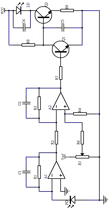
[0008] like figure 1 As shown, a coaxial pigtail laser drive circuit includes a photodetector PD for detecting the output optical power of the laser LD, the positive pole of the photodetector PD is connected to the power ground, and the negative pole of the photodetector PD is integrated with the first The inverting input terminal of the operational amplifier A1 is connected, the inverting input terminal of the first integrated operational amplifier A1 is connected to the output terminal of the first integrated operational amplifier A1 through the first resistor R1, and the non-inverting input terminal of the first integrated operational amplifier A1 is connected to the power supply Connected to the ground, the first capacitor C1 is connected in parallel with the first resistor R1, the output terminal of the first integrated operational amplifier A1 is connected to the inverting input terminal of the second integrated operational amplifier A2 through the second resistor R2, and...


PUM


Abstract

The invention discloses a drive circuit of a coaxial pigtail laser. The drive circuit comprises a photoelectric detector, a pre-amplifying circuit, a secondary amplifying circuit, a reference voltage adjusting circuit, a current drive circuit and the like, wherein the photoelectric detector which is packaged together with the laser is used for detecting photo-power variation of the laser; and photocurrent is generated on the photoelectric detector and has a negative feedback effect on forward current of an LD (Leak Detector) after being amplified, so that light of the laser is stably output. The drive circuit has the advantages of simple circuit, small size, low cost, high reliability, adjustable power and the like.

Description

technical field [0001] The present invention relates to a laser drive circuit. Background technique [0002] The coaxial pigtail laser has the characteristics of small threshold current, built-in InGaAs / PIN backlight monitor diode, high reliability, small package size, long service life, etc., and can be used in the fields of optical communication and optical sensing. [0003] Most of the existing laser drive circuits are numerically controlled, with complex structures and high costs, and are not suitable for direct use as drive circuits for coaxial pigtail lasers. Since the numerical control method will generate a lot of noise during operation, a special circuit is required to eliminate the noise. The numerical control circuit plus the denoising circuit will greatly increase the circuit cost. Therefore, it is very necessary to develop a coaxial pigtailed laser driver with low cost and reliable performance. Contents of the invention [0004] The invention aims at the def...

Claims


Application Information

Patent Timeline
IPC IPC(8): H01S5/042
Inventor 朱惠宗倪新龙许四云邓焯泳冯金垣
Owner SOUTH CHINA UNIV OF TECH
Learn More