Compound model processing method and device for cutter

A technology of surface compounding and treatment methods, which is applied in the direction of manufacturing tools, measuring/indicating equipment, laser welding equipment, etc., can solve the problems of low processing quality, easy wear, and coolant failure, so as to improve chip quality and wear easily , Reduce the effect of blade wear

Active Publication Date: 2013-03-13
JIANGSU UNIV
View PDF8 Cites 44 Cited by
  • Summary
  • Abstract
  • Description
  • Claims
  • Application Information

AI Technical Summary

Problems solved by technology

[0008] Aiming at the problems of tool wear, chipping, low processing quality and coolant failure, the present invention proposes a surface composite modeling treatment method that comprehensively improves the performance of the tool, which facilitates the forced separation of chips and tools, reduces the generation of chip edges, and further It avoids the vibration caused by chip edge and improves chip quality; facilitates chip removal and reduces...

Method used


Image

  • Compound model processing method and device for cutter
  • Compound model processing method and device for cutter
  • Compound model processing method and device for cutter

Examples


specific Embodiment approach

[0036] The specific implementation of the inventive method is as follows:

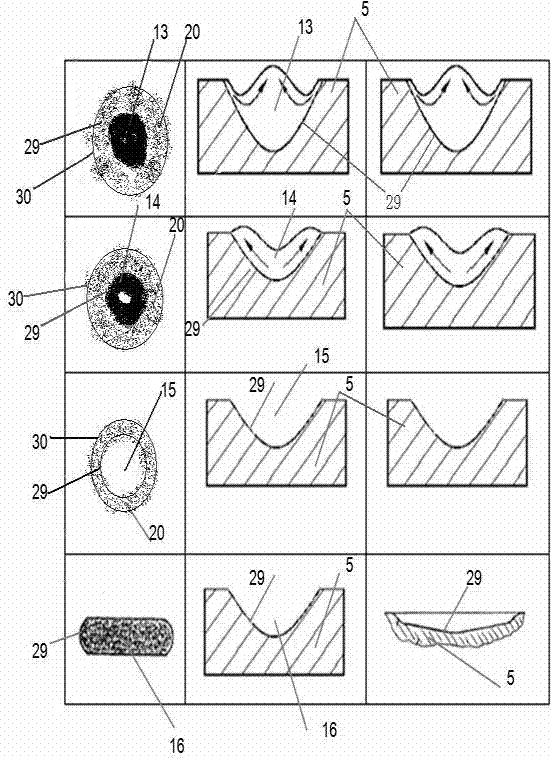
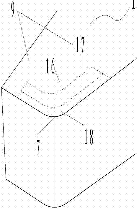
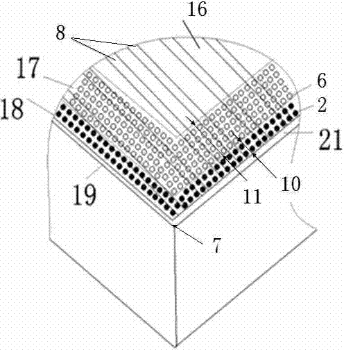
[0037] (a) Divide the area on the surface of the metal cutting tool 1. The machining-affected area 16 is the area on the surface of the tool that is affected by the cutting operation, including the cutting area 18, the main wear area 17 and the extension to other areas on the surface of the tool 1. The extended area It is the position where the coolant on the surface of the tool 1 is easy to reach, and the cutting zone 18 and the main wear zone 17 are the positions where the coolant is not easy to reach or loses quickly; the cutting zone 18 is the area where the task of removing the material of the workpiece 3 to be cut is completed during the cutting process of the tool 1 ; The main wear zone 17 is the area that supports the chip during the cutting process of the tool 1, and the chip begins to separate from the tool in this area; the boundaries of the cutting zone 18 and the main wear zone 17 are paral...

Embodiment 2

[0053] Example two such as Figure 8 , it differs from Embodiment 1 in that: the scanning system in Embodiment 2 is a manipulator 101; the external optical path of the micro-modeling system is realized by an optical fiber 100 with flexibility, and the optical fiber 100 is connected to the laser 47 and the nozzle 48; the laser 47 produces The laser light is transmitted through the optical fiber 100 and the nozzle 48 is held by the manipulator tip 102 . The manipulator 101 communicates with the upper industrial computer, and is controlled by the latter to implement the same compound modeling processing method for the tool surface as in the first embodiment.


PUM

PropertyMeasurementUnit
Power densityaaaaaaaaaa
Depthaaaaaaaaaa
Diameteraaaaaaaaaa

Abstract

The invention provides a compound model processing method and device for a cutter, relating to the active processing of microtexture compound morphologies on the main friction and abrasion surfaces of the cutter, and belonging to the field of machinery manufacture. Three microstructural models, namely micro concave cavities, fused bulges and micro grooves respectively, are processed at the main friction and abrasion parts of the cutter through high energy laser beams or high energy electron beams. With the adoption of the compound model processing method and device for the cutter, the continuous service life of the cutter is prolonged, the cutting quality of the cutter is improved, the surface quality and the cutting and cooling performances after the processing of a workpiece are improved, and the machining cost of metal cutting is lowered. The invention also discloses the processing device for applying the compound mould processing method; and the device is integrated with a high energy technique and a numerical control technique, so that predetermined compound microstructural morphologies and distributions thereof can be processed on the main cutting working face of the cutter efficiently and stably. Processing objects for the method and the device thereof provided by the invention are various cutters during the cutting processing.

Description

technical field [0001] The invention relates to a processing method for compound modeling on the surface of a tool and a device for implementing the processing method. The active processing of the micro-texture composite shape is performed on the main friction and wear surface of the tool, which belongs to the field of mechanical manufacturing. Background technique [0002] Most machining is inseparable from tools and the latter accounts for a large proportion of machining costs. In today's increasingly fierce competition in the machinery industry, the extension of tool life and the improvement of cutting quality have a significant positive effect on enhancing the competitiveness of enterprises. [0003] During cutting, especially under high-speed and heavy-duty cutting conditions, the accumulation of heat on the cutting edge of the tool causes the local temperature of the tool to rise sharply, and chips flow out at high speed. Under the joint action of high temperature, h...

Claims


Application Information

Patent Timeline
IPC IPC(8): B23P17/00B23K26/00B23Q17/00
Inventor 符永宏康正阳符昊华希俊王浩
Owner JIANGSU UNIV
Why Eureka
Try Eureka