Method for using metallurgical fume for coal gasification

A technology of coal gasification and flue gas, which is applied in the manufacture of combustible gas, petroleum industry, joint combustion mitigation, etc., can solve the problem of poor utilization of heat, achieve resource utilization, reduce carbon emissions, and improve utilization efficiency Effect

Inactive Publication Date: 2013-03-13
KUNMING UNIV OF SCI & TECH
View PDF1 Cites 2 Cited by
  • Summary
  • Abstract
  • Description
  • Claims
  • Application Information

AI Technical Summary

Problems solved by technology

In the non-ferrous metallurgy industry, only a few smelters use flue gas waste heat recovery for power generation in the pyrometallurgy process, and many manufacturers still use boiler heating steam-steam dissipation to cool down the flue gas, and the heat in the flue gas has not been well recovered. use

Method used


Image

  • Method for using metallurgical fume for coal gasification
  • Method for using metallurgical fume for coal gasification
  • Method for using metallurgical fume for coal gasification

Examples


Embodiment 1

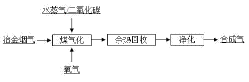
[0019] Embodiment 1: the specific preparation steps of this embodiment are: as figure 1 As shown, the metallurgical flue gas with a temperature of 800 °C is mixed with water vapor, and then the above mixed gas is passed into high-quality anthracite particles for coal gasification reaction, and finally the tail gas obtained after the coal gasification reaction is subjected to waste heat recovery and purification treatment, and finally Get purified CO, H 2 . The reaction conditions and reaction results are shown in Table 1 and Table 2. The coal powder used is 100g of high-quality anthracite, the particle size is 20-40 mesh, the water vapor flow rate: 1 g / min, the oxygen flow rate: 0 Nm 3 / h.

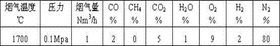
[0020] Table 1 Simulated flue gas flow rate, temperature and composition

[0021]

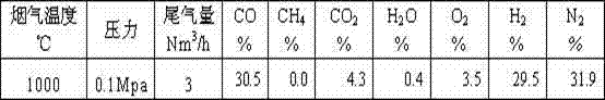
[0022] Table 2 Flow rate, temperature and composition of tail gas after reaction

[0023]

Embodiment 2

[0024] Embodiment 2: the specific preparation steps of this embodiment are: as figure 1 As shown, metallurgical flue gas and water vapor at a temperature of 1000°C are fed into coal for coal gasification reaction, and finally the tail gas obtained after coal gasification reaction is subjected to waste heat recovery and purification treatment, and finally the purified CO, H 2 . The reaction conditions and reaction results are shown in Table 3 and Table 4. The coal powder used is 100g of high-quality anthracite, the particle size is 20-40 mesh, the water vapor flow rate: 1 g / min, the oxygen flow rate: 0 Nm 3 / h.

[0025] Table 3 Simulated flue gas flow rate, temperature and composition

[0026]

[0027] Table 4 Flow rate, temperature and composition of tail gas after reaction

[0028]

Embodiment 3

[0029] Embodiment 3: the specific preparation steps of this embodiment are: as figure 1 As shown, metallurgical flue gas and water vapor at a temperature of 600°C are used to assist the introduction of oxygen, and then the above-mentioned mixed gas is introduced into the coal for coal gasification reaction, and finally the tail gas obtained after the coal gasification reaction is subjected to waste heat recovery and purification treatment , and finally the purified CO, H 2 . The reaction conditions and reaction results are shown in Table 5 and Table 6. The coal powder used is 100g of high-quality anthracite, the particle size is 20-40 mesh, the water vapor flow rate: 1 g / min, the oxygen flow rate: 5 Nm 3 / h.

[0030] Table 5 Simulated flue gas flow rate, temperature and composition

[0031]

[0032] Table 6 Flow rate, temperature and composition of tail gas after reaction

[0033]


PUM


Abstract

The invention relates to a method for using metallurgical fume for coal gasification, belonging to the fields of metallurgical engineering as well as energy and chemical industry. The method comprises the following steps of: mixing metallurgical fume with a temperature below 600 DEG C with one of vapour and carbon dioxide or both the vapour and the carbon dioxide in any ratio; charging oxygen for support in the case that the temperature of the metallurgical fume is below 800 DEG C; charging the mixed gas in coal and performing a coal gasification reaction; performing waste heat recovery and purification treatment on the tail gas obtained after the coal gasification reaction; and finally obtaining one or two of the purified CO and H2. A real-time adjustment can be performed to utilize the fume with an unstable temperature; combustible ingredients in the fume can be efficiently utilized on the aspects of resource reuse or calorific value increase; and the utilization efficiency of coal can be increased in combination with fume utilization.

Description

technical field [0001] The invention relates to a new method for resource utilization of metallurgical flue gas, which belongs to the fields of metallurgical engineering and energy chemical industry. technical background [0002] Energy resources are the basis of economic development. Only from the energy resources currently in our country, the remaining recoverable reserves of coal are about 110 billion tons, the remaining recoverable reserves of oil are about 2.4 billion tons, and the remaining recoverable reserves of natural gas are about 2 trillion cubic meters. The possessions are respectively 70%, 10% and 5% of the world average level. With the rapid development of my country's economy and the improvement of people's living standards, my country's energy demand will continue to grow. To solve the current and future energy supply problems in our country and ensure stable and sustainable economic development, in addition to changing the mode of economic growth and impr...

Claims


Application Information

Patent Timeline
Patent Type & Authority Applications(China)
IPC IPC(8): C10J3/00C10J3/72
CPCY02E20/18Y02P20/129
Inventor 李孔斋祝星王华魏永刚胡建杭
Owner KUNMING UNIV OF SCI & TECH
Why Eureka
Try Eureka