Interference lithography system and method based on spatial light modulator

A technology of spatial light modulator and interference lithography, which is applied in the field of interference lithography system based on spatial light modulator, can solve the problems of complex system, low efficiency and no simplicity, and achieve the effect of high-efficiency lithography

Inactive Publication Date: 2013-03-13
SHENZHEN SHENDA AURORA TECH
View PDF5 Cites 14 Cited by
  • Summary
  • Abstract
  • Description
  • Claims
  • Application Information

AI Technical Summary

Problems solved by technology

Among them, the one-dimensional grating used in the grating diffraction spectroscopic method has a fixed grating constant. In order to change the angle of the interfering light, for example, the method of replacing multiple one-dimensional gratings must be manually replaced and repeated exposures. Exposure only records a point and not an image, so it's very inefficient
However, the prism refraction spectroscopic method requires the use of multiple optical elements, multiple refraction and reflection of light, and the use of electromechanical systems to control the positioning and movement of these optical elements to control the beam direction, so the system is more complicated, and the moving speed of the optical elements is not fast. High, there is a large loss of light energy in multiple refraction and reflection
The prism refraction spectroscopic method can control

Method used


Image

  • Interference lithography system and method based on spatial light modulator
  • Interference lithography system and method based on spatial light modulator
  • Interference lithography system and method based on spatial light modulator

Examples


Embodiment 1

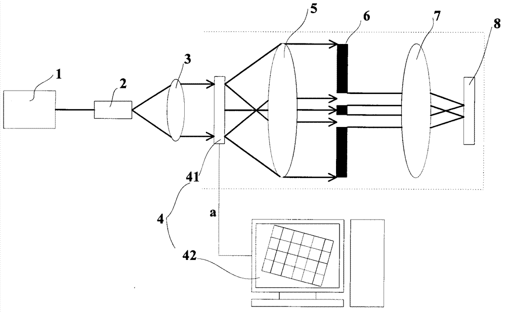
[0043] This embodiment provides an interference lithography system and method based on a spatial light modulator. see figure 1As shown, it is a schematic structural diagram of an interference lithography system based on a spatial light modulator in Embodiment 1 of the present invention. The system includes in order according to the direction of beam propagation: a light source, a beam expander 2, a collimator lens 3, a spatial light modulation device 4, and a Fourier Transformation lens 5, Fourier transform spectrum filter baffle 6, imaging mirror, photoresist dry plate, wherein the photoresist dry plate is a glass dry plate coated with photoresist. Interference lithography needs to use a light source with strong coherence. In this embodiment, in order to achieve higher definition, the light source is laser 1, and the irradiation beam emitted by laser 1 is laser. The spatial light modulation device 4 includes a spatial light modulator and a computer 42. The spatial light modu...

Embodiment 2

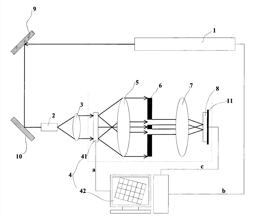
[0065] The difference between this embodiment and Embodiment 1 is that when the optical path of the laser is not in the same direction as other optical elements such as the beam expander, it is necessary to add a plane reflector so that the beam can be incident on the beam expander; this embodiment also adds a light Resist dry plate mobile unit for high resolution pattern exposure. Only the different parts of this embodiment and the first embodiment will be described below, and the same parts will not be described again.

[0066] see image 3 As shown, it is a schematic structural diagram of an interference lithography system based on a spatial light modulator in Embodiment 2 of the present invention. In this embodiment, on the basis of Embodiment 1, a first plane mirror 9, a second plane mirror 10, and a photoresist dry plate moving device are added. In this embodiment, the photoresist dry plate is a holographic dry plate 8, Therefore, the photoresist dry plate moving devic...


PUM


Abstract

The invention relates to the technical field of lithography and provides an interference lithography system based on a spatial light modulator. According to the system, illumination beams transmitted from a light source become divergent light through a beam expander, the divergent light becomes parallel light through a collimating lens, the parallel light enters the spatial light modulator, the spatial light modulator performs image information modulation on the parallel light, a computer controls the spatial light modulator to display patterns, the parallel light becomes diffraction light after being subjected to diffraction splitting through the patterns displayed on the spatial light modulator, the diffraction light forms a spectral surface pattern on a back focal plane of a Fourier transform lens after passing through the Fourier transform lens, the diffraction light with required series is controlled to pass through by a Fourier transform spectral surface filtering baffle, and the diffraction light passing through the Fourier transform spectral surface filtering baffle is imaged with interference on a photoresist dry plate through an imaging mirror. The patterns displayed on the spatial light modulator are controlled through the computer, and the functions of image information modulation and diffraction splitting are simultaneously finished by the spatial light modulator.

Description

technical field [0001] The present invention relates to the technical field of photolithography, in particular to an interference photolithography system and method based on a spatial light modulator. Background technique [0002] Optical lithography technology can be used in the production of diffraction gratings, laser holograms, holographic optical components and other products, so it has been widely used in lithography plate making, anti-counterfeiting, micro-optics and other fields. An important factor in the rapid development of science and industry such as micro-processing technology and microelectronics industry. Many countries, including my country, are vigorously developing various optical lithography systems. [0003] Lithography technology has experienced the development from traditional contact exposure, to optical projection lithography, and to the current advanced interference lithography, imaging interference lithography, holographic lithography, atomic lith...

Claims


Application Information

Patent Timeline
IPC IPC(8): G03F7/20G02B27/10
Inventor 王笑冰李建兵张海明
Owner SHENZHEN SHENDA AURORA TECH
Why Eureka
Try Eureka