Power supply system for drilling machine grid electricity

A technology of power supply system and grid power, applied in the direction of panel/switch station circuit device, substation/switchgear cooling/ventilation, substation/switchgear board/panel/desk, etc., can solve low energy efficiency, pollution, high loss and other problems to achieve the effect of improving economic benefits, reducing noise pollution and low noise

Inactive Publication Date: 2013-03-13
海尔海斯(西安)控制技术有限公司
View PDF0 Cites 0 Cited by
  • Summary
  • Abstract
  • Description
  • Claims
  • Application Information

AI Technical Summary

Problems solved by technology

[0003] The purpose of the present invention is to overcome the problems of low energy efficiency, high loss and pollution caused in the process of fuel oil power generation, and to provide a grid power supply system for drilling rigs. This device makes drilling work safer, more efficient and environmentally friendly, and improves economic benefits

Method used


Image

  • Power supply system for drilling machine grid electricity
  • Power supply system for drilling machine grid electricity
  • Power supply system for drilling machine grid electricity

Examples


Embodiment 1

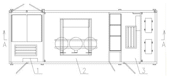
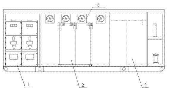
[0029] like figure 2 As shown, the grid power supply system of the drilling rig includes at least a high-voltage part 1, a transformer part 2 and a low-voltage part 3. It is connected to the input end of the transformer part 2, and the output end of the transformer part 2 is electrically connected to the low voltage part 3, and the low voltage part is distributed with an output interface 4.

[0030] The output interface 4 is the interface of winch, mud pump, turntable and solids control MCC respectively.

[0031] The high-voltage part 1, transformer part 2 and low-voltage part 3 of the entire drilling rig network power supply system are fixed in the room. The room is 8000mm long, 2900mm wide and 3100mm high. The high-strength and high-protection frame structure control room can meet the operation requirements of frequent activities in the oil field.

[0032] This device will directly obtain power from the industrial power grid. After being connected to the high-voltage part...

Embodiment 2

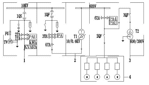
[0034] The high-voltage part includes the high-voltage incoming line metering cabinet and the high-voltage outgoing line cabinet, which are fixed at the end of the control room. The high-voltage incoming line metering cabinet is KYN28-12 or KYN61-40.5 armored AC metal-enclosed switchgear. The design of the switchgear complies with GB3906-2006 of "3.6-40.5kV AC metal-enclosed switchgear and control equipment".

[0035] like figure 1 As shown, the high-voltage incoming line metering cabinet is equipped with: handcart type voltage transformer (TV) model: JDZ12-10 or JDZX9-35; metering current transformer (1TA, 2TA) model: LZZBJ9-12 or LZZBJ9- 40.5; the electric energy meter (KWH and KWARH) model is: DSZ331; the voltmeter (PAU) model is: APZ194U, to complete the household entry and measurement of high-voltage network power.

[0036] The industrial high-voltage power grid is connected to the inlet of the high-voltage part of the control room through overhead lines, and connected ...

Embodiment 3

[0041] like figure 1 and figure 2 As shown, the transformer (T1) of transformer part 2 is a 4000kVA 10kV / 0.6kV or 35KV / 0.6KV transformer, located in the middle of the control room. The 10KV or 35KV high-voltage power of the high-voltage outlet of the high-voltage part 1 is connected to the primary side of the transformer, and the secondary side is converted into a low-voltage power supply of 0.6kV or 0.69KV and connected to the low-voltage part 3, which is provided for the system through the output interface 4 of the low-voltage part 3. power energy. The transformer can adopt the on-load voltage regulation mode, which can realize voltage regulation under load, avoid the risk of voltage fluctuation caused by load fluctuation and industrial and mining conversion, and make the power source have good followability under the condition of high load change rate. Avoid the change of the grid voltage caused by the load change, so that the load equipment can work better in the rated ...


PUM


Abstract

The invention relates to a power supply system for drilling machine grid electricity. The power supply system at least comprises a high-voltage part, a transformer part and a low-voltage part and is characterized in that a high-voltage incoming wire metering cabinet of the high-voltage part is connected with an external industrial power grid, the output end of a high-voltage wire outgoing cabinet of the high-voltage part is connected with the input end of a transformer, the output end of the transformer is connected with the low-voltage part, and output ports are distributed in the low-voltage part. According to the invention, the problems of low energy efficiency, high loss and pollution caused in a fuel oil power generation process are solved, and the power supply system ensures that well drilling work is safer, more efficient and more environmentally-friendly, and is beneficial to increase of economic benefits.

Description

technical field [0001] The invention relates to the field of petroleum drilling and production, in particular to a grid power supply system for drilling rigs that provides power energy for drilling equipment. Background technique [0002] With the rapid development of my country's economy, the demand for energy is increasing, especially the demand for oil energy. At present, most of the drilling and production equipment in the domestic and foreign markets use diesel generators as the power source to provide power for the drilling rig equipment. Drilling mines not only have a heavy load, but also have a high rate of change in load. Under such variable working conditions, diesel power units have low efficiency, large losses, and high costs, accompanied by high-decibel noise pollution and a large number of Exhaust emissions are very polluting to the environment. Contents of the invention [0003] The purpose of the present invention is to overcome the problems of low energy...

Claims


Application Information

Patent Timeline
Patent Type & Authority Applications(China)
IPC IPC(8): H02B1/24H02B1/04H02B1/56H02B1/20
Inventor 巴平基吴景卫金涛陈谋张峰
Owner 海尔海斯(西安)控制技术有限公司
Why Eureka
Try Eureka