
Small-size resonator and magnetic coupling resonance wireless energy transmission system

A technology of wireless energy transmission and magnetic coupling resonance, applied in electromagnetic wave systems, transformers, inductors, etc., can solve the problems of lack of relevant literature, poor repeatability, and unfavorable system miniaturization.

Inactive Publication Date: 2013-03-20
HEBEI UNIV OF TECH
View PDF4 Cites 13 Cited by
  • Summary
  • Abstract
  • Description
  • Claims
  • Application Information

AI Technical Summary

Problems solved by technology

(2) Medium-distance wireless energy transmission can be carried out. Once the traditional method increases the transmission distance, the transmission efficiency will drop sharply
The magnetically coupled inductive coils of traditional implantable medical devices for percutaneous energy transmission are mostly wound by machines or manually, which has poor repeatability and difficulty in inductance control, and the coils with magnetic cores are large in size, which is not conducive to the miniaturization of the system
[0005] At this stage, Witricity wireless energy transmission technology is still in its infancy, and relevant theoretical and experimental research is still relatively lacking, especially for Witricity wireless energy transmission of implanted devices in the body, there are almost no relevant literature

Method used


Image

  • Small-size resonator and magnetic coupling resonance wireless energy transmission system
  • Small-size resonator and magnetic coupling resonance wireless energy transmission system
  • Small-size resonator and magnetic coupling resonance wireless energy transmission system

Examples


Embodiment Construction

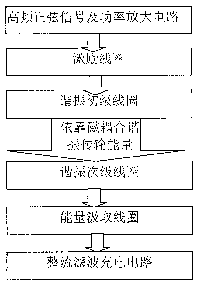
[0020] The structure of the magnetically coupled resonant wireless energy transfer system is as follows: figure 1 As shown, the entire wireless energy transfer system consists of four main parts: high-frequency sinusoidal signal generation and power amplification circuit, excitation coil and resonant primary coil (coil 1), resonant secondary coil (coil 2) and energy extraction coil and rectifier Filter charging circuit. If the resonant primary and secondary coils are directly connected to the circuit, the resonant frequency of the Witricity system will be greatly disturbed, so an excitation coil and an energy extraction coil are added, wherein the excitation coil is connected to the power amplifier circuit, and the energy extraction coil is connected to the load. The excitation coil and the energy extraction coil are wound by copper wire with a diameter of 1 mm into a helical coil with a diameter of 5 cm and 3 turns, and energy is transferred to the resonant primary and second...


PUM


Abstract

Magnetic coupling resonance wireless energy transmission is a new technology which utilizing magnetic coupling resonance to achieve middle-distance electric energy wireless transmission, and has good application prospects. The invention provides a small-size plane-spiral resonance coil made by a printed board directly, the front face and the back face of the coil are all coated with copper, inductance generated on a front conductor layer and capacitance generated on an overlapped section of the front conductor layer and a back conductor layer form a needed resonator through a complex series-parallel connection circuit for energy transmission, and the size of the resonator is only 1.35 cm<3>. Through establishment of human head three-dimensional numerical model and implantation of a coil model into a body, a time-domain finite difference method is applied to the calculate head specific absorption rate and the electric-field magnetic field strength. Results show that when the magnetic coupling resonance wireless energy transmission technology is applied for the energy transmission of components implanted in the head, the I0g specific absorption rate (SAR) average value of the human head is 9.2627*10-6W / kg, the maximum value of root-mean-square of the electric-field magnetic field strength is respectively 4.64 V / m and 0.057 A / m, and the values are lower than the international safety limit standard.

Description

technical field [0001] The invention relates to a small-sized resonator and a magnetic coupling resonance wireless energy transmission system. Background technique [0002] With the development of science and technology, implanted electronic medical products with various functions continue to enter people's lives. They play a huge role in disease diagnosis, treatment, limb correction, rehabilitation, etc., bringing patients life It is convenient and even extends the life of the patient. [0003] Power supply technology is one of the most critical technologies among many technologies for implanting electronic devices. Although there are many possible power supply methods for implanted electronic devices, battery-powered power supply mode is generally used in various biological devices at present. Although the battery capacity is constantly increasing, there is always a risk of power depletion due to its lack of real-time energy supply function. Dilemma. Wireless power tran...

Claims


Application Information

Patent Timeline
IPC IPC(8): H02J17/00H01F38/14H02J50/12
Inventor 徐桂芝赵军李烜
Owner HEBEI UNIV OF TECH
Learn More