Fusing method of laser welding with filler wires using double TIG welding torches

A technology of laser wire filling and welding torch, which is applied in the direction of laser welding equipment, welding equipment, arc welding equipment, etc., can solve the problems of large deformation of welding joints, high precision requirements in welding wire, and poor mechanical properties of welds, so as to reduce heat loss. Effect of input, reduction of weld porosity, and improvement of mechanical properties

Active Publication Date: 2013-03-27
HARBIN INST OF TECH
View PDF7 Cites 17 Cited by
  • Summary
  • Abstract
  • Description
  • Claims
  • Application Information

AI Technical Summary

Problems solved by technology

[0005] The present invention aims to solve the problems of high wire centering accuracy requirements, large deformation of welded joints and poor mechanical properties of weld seams

Method used


Image

  • Fusing method of laser welding with filler wires using double TIG welding torches
  • Fusing method of laser welding with filler wires using double TIG welding torches
  • Fusing method of laser welding with filler wires using double TIG welding torches

Examples


specific Embodiment approach 1

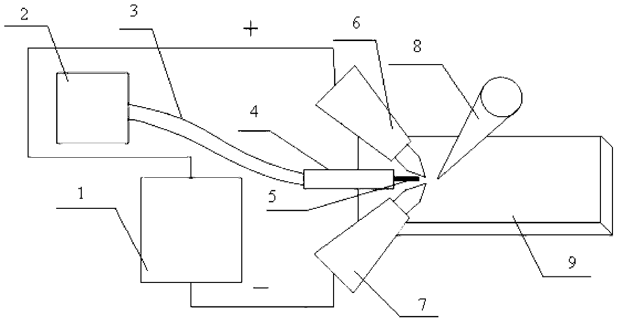
[0024] Specific embodiment one: a kind of fuse method that adopts the laser filler wire welding of double TIG welding torch in the present embodiment is carried out according to the following steps:

[0025] 1. When the base material is magnesium, aluminum and its alloys, connect two TIG welding guns to the positive and negative poles of the TIG power supply respectively, and connect the negative pole of the TIG power supply to the base metal, and the TIG power supply adopts a DC output form;

[0026] 2. Start the laser to make the laser form a molten pool on the base material. The output type of the laser adopts continuous output or pulse output, and the laser power is 500W~5000W;

[0027] 3. Turn on the shielding gas so that the shielding gas is ejected from the coaxial wire feeding gas nozzle, and then connect the TIG power supply to start the arc between the two TIG welding torches, start the wire feeding system so that the welding wire is continuously sent out, and adjust ...

specific Embodiment approach 2

[0036] Embodiment 2: The difference between this embodiment and Embodiment 1 is that the output current of the TIG power supply in Step 1 is 10A~120A. Other steps and parameters are the same as those in Embodiment 1.

specific Embodiment approach 3

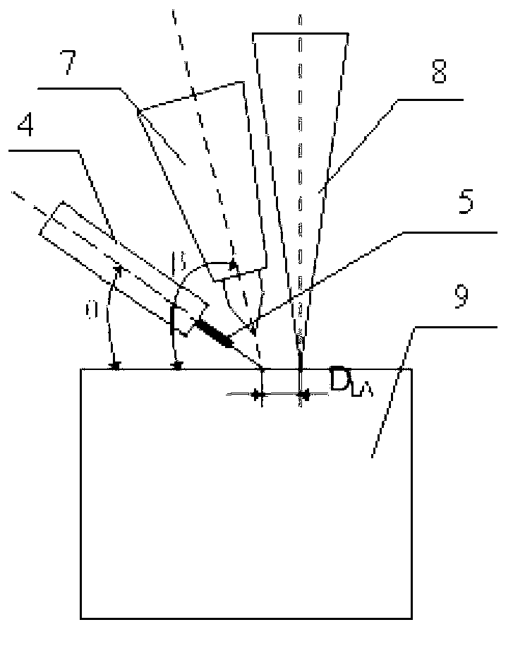
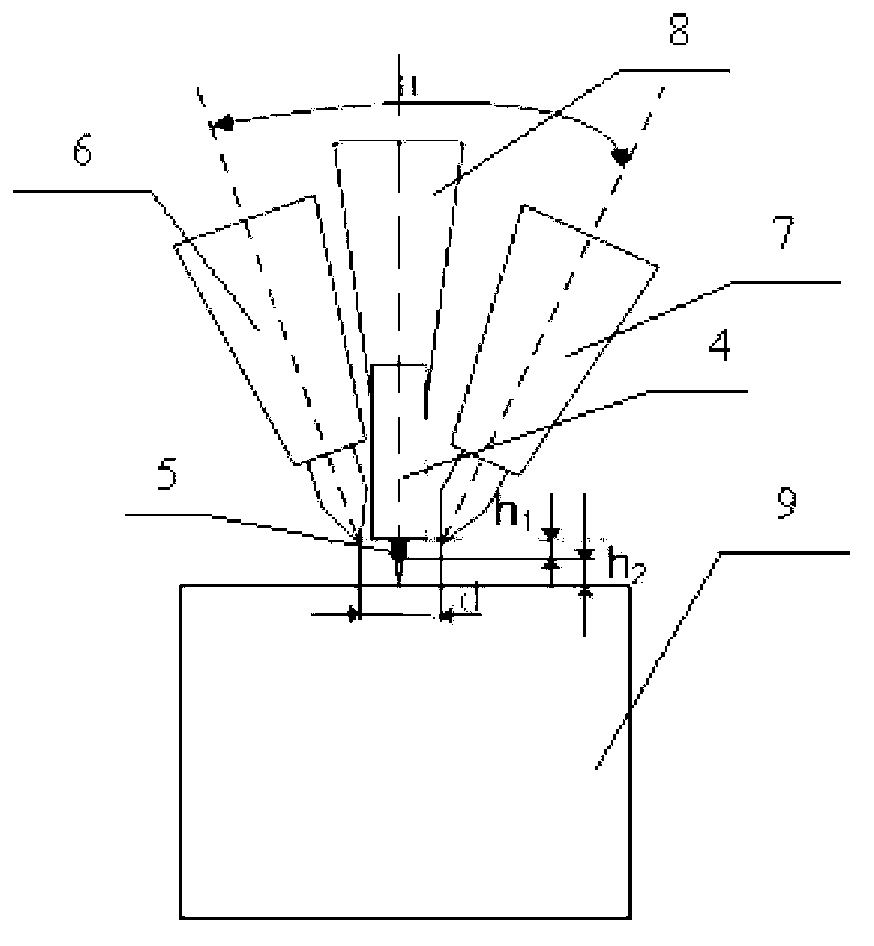
[0037] Specific embodiment three: the difference between this embodiment and specific embodiment one or two is that the horizontal distance between the two TIG welding torches in step one is 0 mm ~ 8 mm, and the angle α between the two TIG welding torches is 10 ° ~ 160 °, The angle β between the plane where the two TIG welding torches are located and the base metal is 30°-90°. Other steps and parameters are the same as those in Embodiment 1 or Embodiment 2.


PUM


Abstract

The invention discloses a fusing method of laser welding with filler wires using double TIG welding torches, which relates to a fusing method of laser welding with filler wires, and mainly aims to solve the problems of high requirement on accuracy of alignment of a welding wire, large deformation of a welding joint and poor mechanical performance of a welding seam of a normal fusing method adopted by the conventional wire filling laser welding process. The fusing method comprises the following steps of: respectively connecting the two TIG welding torches with positive and negative poles of a TIG power supply; starting a laser device to form a welding pool on a workpiece to be welded by laser; and starting shielding gas which is sprayed out from a coaxial wire and gas feeding nozzle, connecting the TIG power supply to implement arc striking between the two welding torches, starting a wire feeding system to send out welding wires continuously, and adjusting the output current and the wire feeding speed of the TIG power supply to ensure that an electric arc fuses the welding wire stably, wherein the protection gas is not introduced into the two TIG welding torches independently. The fusing method can be applied to the field of metal laser filling welding connection engineering.

Description

technical field [0001] The invention relates to a fuse method for laser wire filling welding. Background technique [0002] Laser wire-filling welding has strict requirements on wire-feeding accuracy. During laser wire-filling welding, the fluctuation of wire-feeding position and wire-feeding speed, and the reflection of welding wire to light will cause changes in the laser energy entering the workpiece. Moreover, for reliable fuse, the tip of the welding wire basically touches the edge of the keyhole, which is likely to cause great disturbance to the stability of the molten pool and the keyhole. The stable melting and filling of welding materials are the bottlenecks in the application of laser filler wire welding technology. [0003] In the current arc-assisted fuse method of laser filler wire welding, since the TIG arc or MIG arc directly acts on the base metal, it is easy to cause too much heat input to the base metal, which will cause deformation of the base metal and e...

Claims


Application Information

Patent Timeline
IPC IPC(8): B23K28/02B23K9/167B23K26/20B23K26/24
Inventor 李俐群林尚扬彭进陈彦宾
Owner HARBIN INST OF TECH
Why Eureka
Try Eureka