Method and equipment for producing high-quality sponge iron for reduced iron powder

A technology of reduced iron powder and sponge iron, which is applied in the improvement of process efficiency, furnace type, furnace and other directions, can solve the problems of increased labor intensity of production personnel, large dust pollution, and low utilization of heat energy, and achieves reduced labor intensity of workers, Improve the effect of comprehensive utilization and production environment improvement

Inactive Publication Date: 2013-03-27
武汉桂坤科技有限公司
View PDF6 Cites 9 Cited by
  • Summary
  • Abstract
  • Description
  • Claims
  • Application Information

AI Technical Summary

Problems solved by technology

[0005] 1. The operation of the mechanized tank loading and unloading device is unstable, so many enterprises have to change to manual tank filling, which increases the labor intensity of production personnel; 2. The production and operation cost of the tunnel kiln is high, because the reaction tank on the trolley has to go through "preheating" continuously →High temperature→cooling” so that the service life of the reaction tank is very low, and the loss of refractory materials of the production ton of iron powder reaction tank accounts for about 1 / 3 of the cost. At the same time, the reprocessing of damaged reaction tanks is very troublesome and easily causes environmental pollution; 3. The production environment of the tunnel kiln is poor, and the dust pollution in the process of loading and unloading the tank is large; 4. The degree of mechanization is not high, and the production efficiency is low; 5. The floor area is large; 6. The utilization of heat energy is low

Method used


Image

  • Method and equipment for producing high-quality sponge iron for reduced iron powder
  • Method and equipment for producing high-quality sponge iron for reduced iron powder

Examples


Embodiment Construction

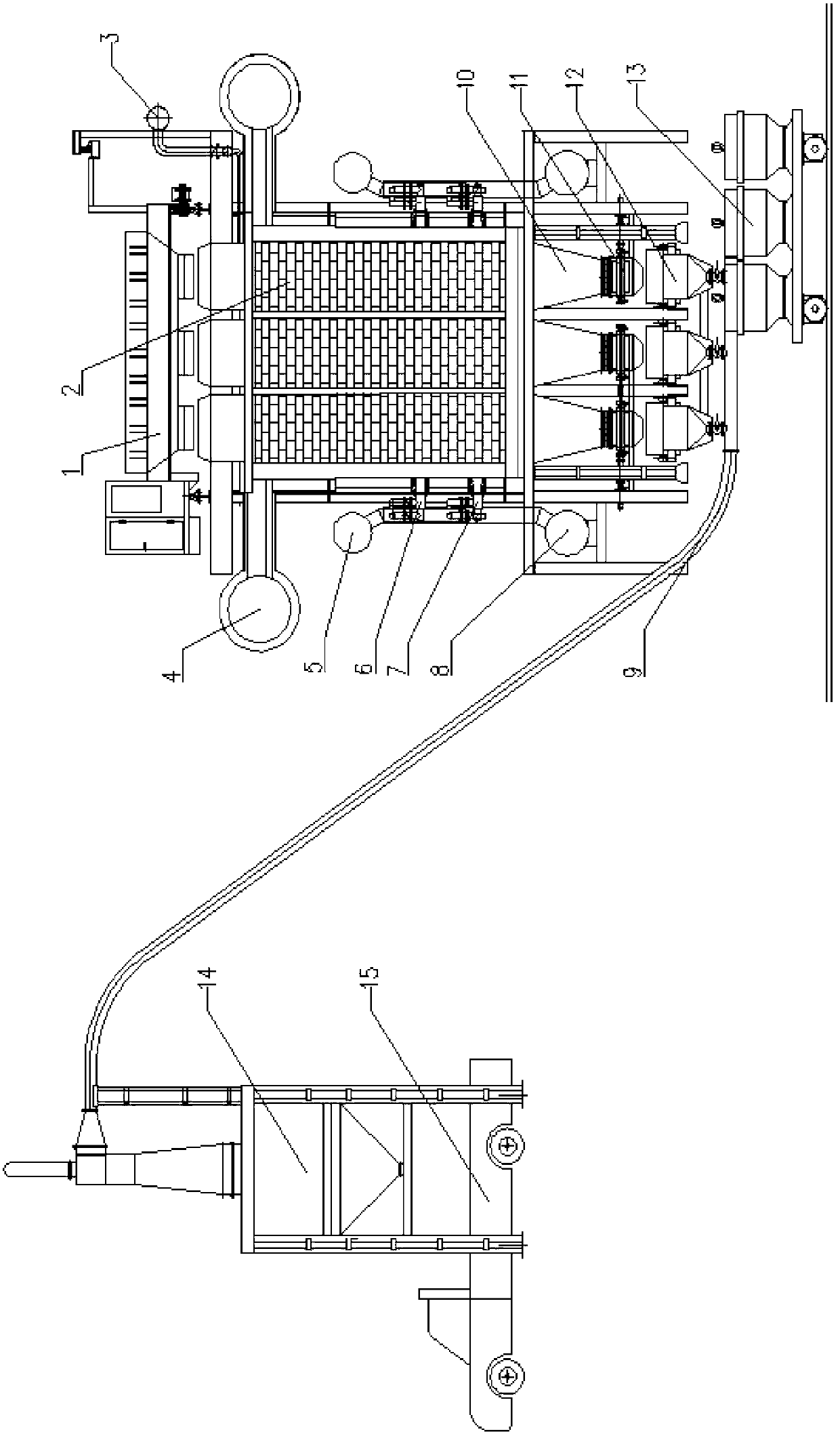
[0032] The present invention will be further described in conjunction with the accompanying drawings.

[0033] Such as figure 1As shown, the present invention includes anti-segregation cloth trolley 1, combined reaction tank shaft furnace 2, gas recovery system 3, smoke exhaust system 4, gas system 5, special burners (6, 7), air preheating system 8, vacuum load Pressure suction system 9, cooling system 10, frequency conversion speed regulation discharge system 11, rolling screening system 12, storage tank 13, storage bin 14, anti-segregation distribution trolley 1, gas recovery system 3 are respectively installed in the combined reaction tank The top of the shaft furnace, the smoke exhaust system 4, the gas system 5, the special burners (6, 7), and the air preheating system 8 are respectively installed around the shaft furnace of the combined reaction tank, and the cooling system 10 is installed at the outlet of the shaft furnace of the combined reaction tank. Between the fee...


PUM


Abstract

The invention relates to a method and equipment for producing high-quality sponge iron for reduced iron powder. The method comprises the steps of: preparing composite solidified pellets by iron ore concentrate powder; mixing the composite solidified pellets or iron stones with a solid reducing agent, adding the mixture into a shaft furnace reaction chamber of a combined reaction tank; heating furnace burdens at a preheating section in the reaction chamber to 800-900 DEG C, and then at a reducing section to 1100-1200 DEG C to carry out reduction reaction for 12-18h; cooling the reacted materials through a cooling section, and then enabling the materials to enter a rolling screening system through a frequency control discharging system for online screening; after screening, conveying the waste reducing agent to a storage bin through a vacuum negative-pressure suction system; and carrying out different normal aftertreatments on the sponge iron obtained by screening according to used different raw materials to obtain the reduced iron powder or a sponge iron briquette. According to the method and the equipment for producing the high-quality sponge iron for the reduced iron powder, the production process is automatically controlled, the mechanization degree is high, the labor intensity of workers is reduced, the production environment is improved, the sponge iron pellets and the reducing agent are separated by the automatic screening and vacuum negative-pressure suction systems, a part of reducing agent is recycled, and thus the energy consumption is reduced.

Description

technical field [0001] The invention relates to a method and supporting equipment for producing high-quality sponge iron for reduced iron powder, which can use super iron concentrate powder / rolled steel scale and other iron-containing oxides (Fe≥71.5%) to produce reduced iron powder that meets the requirements of the powder metallurgy industry. At the same time, ordinary iron concentrate powder / high-grade lump ore (Fe≥68%) can also be used to produce steel-making sponge iron for the steel industry. Background technique [0002] Direct reduced iron, referred to as DRI (Direct Reduction Iron), also known as sponge iron, is a metallurgical product produced by solid-state direct reduction of iron-containing oxides with low impurity content such as high-grade iron ore, pellets or rolled steel scale. With stable chemical composition and low impurity content, it can be used as a substitute for high-quality steel scrap. Adding direct reduced iron in steelmaking is one of the importa...

Claims


Application Information

Patent Timeline
Patent Type & Authority Applications(China)
IPC IPC(8): C21B13/02
CPCY02P10/20
Inventor 李森蓉李雄
Owner 武汉桂坤科技有限公司
Why Eureka
Try Eureka