Zero-voltage switching energy storage bridge-type inverter without additional voltage and modulation method for inverter

A technology of zero-voltage switching and additional voltage, which is applied in the direction of high-efficiency power electronic conversion, electrical components, and conversion of AC power input to DC power output. It can solve the problems of large switching losses of devices, reduce circuit efficiency, and limit operating frequency. Improve power density, improve circuit efficiency, and improve the effect of operating frequency

Active Publication Date: 2013-03-27
SHANGHAI JIAO TONG UNIV
View PDF2 Cites 18 Cited by
  • Summary
  • Abstract
  • Description
  • Claims
  • Application Information

AI Technical Summary

Problems solved by technology

This single-phase battery energy storage inverter can realize the function of grid-connected power generation, and can also run independently with load, but the circuit works in a hard switching state, and there is a problem of rever

Method used


Image

  • Zero-voltage switching energy storage bridge-type inverter without additional voltage and modulation method for inverter
  • Zero-voltage switching energy storage bridge-type inverter without additional voltage and modulation method for inverter
  • Zero-voltage switching energy storage bridge-type inverter without additional voltage and modulation method for inverter

Examples


Embodiment Construction

[0024] The present invention will be described in detail below in conjunction with specific embodiments. The following examples will help those skilled in the art to further understand the present invention, but do not limit the present invention in any form. It should be noted that those skilled in the art can make several modifications and improvements without departing from the concept of the present invention. These all belong to the protection scope of the present invention.

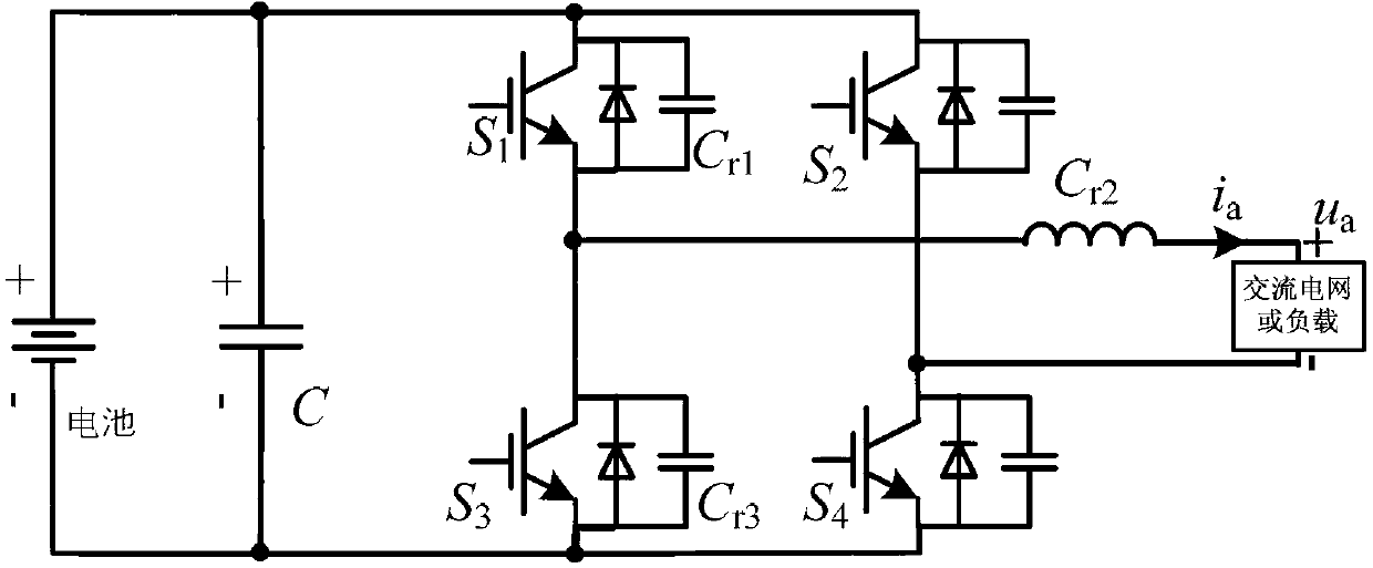
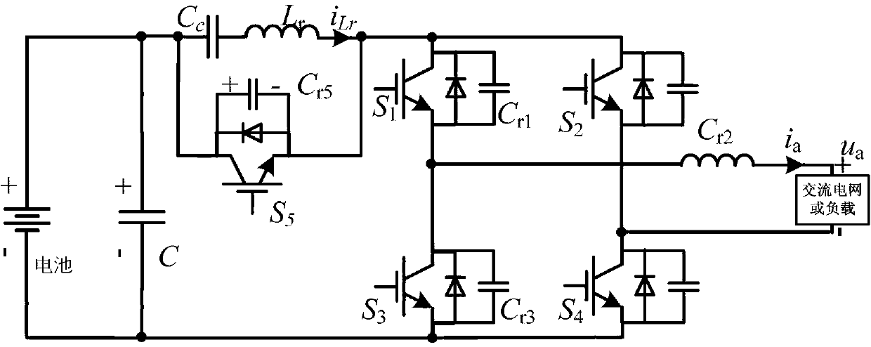
[0025] refer to figure 2 , a zero-voltage switching energy storage bridge inverter without additional voltage, including the inverter DC side battery, DC capacitor, four fully controlled main switches S with anti-parallel diodes 1 ~S 4 The single-phase bridge arm is connected to the output filter inductance L between the midpoint of the bridge arm and the AC grid or AC load, wherein: the four main switches S of the single-phase bridge arm 1 ~S 4 A capacitor is connected in parallel at both end...


PUM


Abstract

The invention discloses a zero-voltage switching energy storage bridge-type inverter without additional voltage and a modulation method for the inverter. The zero-voltage switching energy storage bridge-type inverter comprises a direct-current-side energy storage battery, direct-current capacitors, an alternating-current filter inductor and a single-phase bridge arm. The single-phase bridge arm comprises four fully-controlled main switches with antiparallel diodes, an auxiliary switch with an antiparallel diode is connected between the energy storage battery and a direct-current bus of the single-phase bridge arm, the capacitors are respectively connected to two ends of each main switch and two ends of the auxiliary switch in parallel, the two ends of the auxiliary switch are connected with a resonance branch circuit, and a resonance inductor and a clamping resistor are serially connected to form the resonance branch circuit. The zero-voltage switching energy storage bridge-type inverter and the modulation method have the advantages that the zero-voltage switching energy storage bridge-type inverter can run independently in an on-load manner or run in a grid-connected manner, and is simple in structure, power flows in two directions, and a storage battery can be charged and discharged; the sinusoidal pulse width modulation method is implemented for the main switches, and modulation signals of the auxiliary switch are synchronous with the main switches; zero-voltage switching of all the main switches can be realized only by one-step action of the auxiliary switch in each switching period, reverse recovery current of the antiparallel diode of each main switch is suppressed, the zero-voltage switching energy storage bridge-type inverter is low in switching loss, high in circuit efficiency and beneficial to increasing working frequency, and the power density is increased.

Description

technical field [0001] The invention relates to a battery energy storage inverter, in particular to a circuit topology and a modulation method of a zero-voltage switching battery energy storage bridge inverter with bidirectional flow of energy without additional voltage stress. Background technique [0002] A single-phase battery energy storage inverter with the function of grid-connected power generation and independent operation with load, its circuit is as follows figure 1 As shown, it consists of four fully controlled main switches with anti-parallel diodes (S 1 ~S 4 ) constitutes a single-phase bridge arm, connected to the output filter inductance (L) between the midpoint of the bridge arm and the AC grid or AC load. This single-phase battery energy storage inverter can realize the function of grid-connected power generation, and can also run independently with load, but the circuit works in a hard switching state, and there is a problem of reverse recovery of the dio...

Claims


Application Information

Patent Timeline
IPC IPC(8): H02M7/521H02M7/516H02J3/38
CPCY02B70/1491Y02B70/10
Inventor 李睿梁星王艺翰蔡旭
Owner SHANGHAI JIAO TONG UNIV
Why Eureka
Try Eureka