
Narrow gap multi-pass laser welding method for thick plate

A laser welding and laser technology, used in laser welding equipment, welding equipment, manufacturing tools, etc., to achieve the effect of realizing the control of weld composition and joint performance, the flexibility of size and operation, and the improvement of production efficiency

Inactive Publication Date: 2013-04-03
HUAZHONG UNIV OF SCI & TECH
View PDF9 Cites 31 Cited by
  • Summary
  • Abstract
  • Description
  • Claims
  • Application Information

AI Technical Summary

Problems solved by technology

[0005] In view of the deficiencies in the technical background, the purpose of the present invention is to provide a narrow-gap multi-pass laser welding method for thick plates. The present invention solves the problem of high-efficiency and high-quality welding of thick plates, and can obtain small welding deformation and gap bridging High quality and efficient welded joints for heavy plates

Method used


Image

  • Narrow gap multi-pass laser welding method for thick plate
  • Narrow gap multi-pass laser welding method for thick plate
  • Narrow gap multi-pass laser welding method for thick plate

Examples


example 1

[0036] Welding material: marine structural steel plate (150*75*18mm 3 )

[0037] During self-fusion welding: V welding = 0.5m / min, p = 3kw

[0038] When filling wire welding: V welding = 0.4m / min, V delivery = 4.2m / min, P = 4kw, Δf = -1mm,

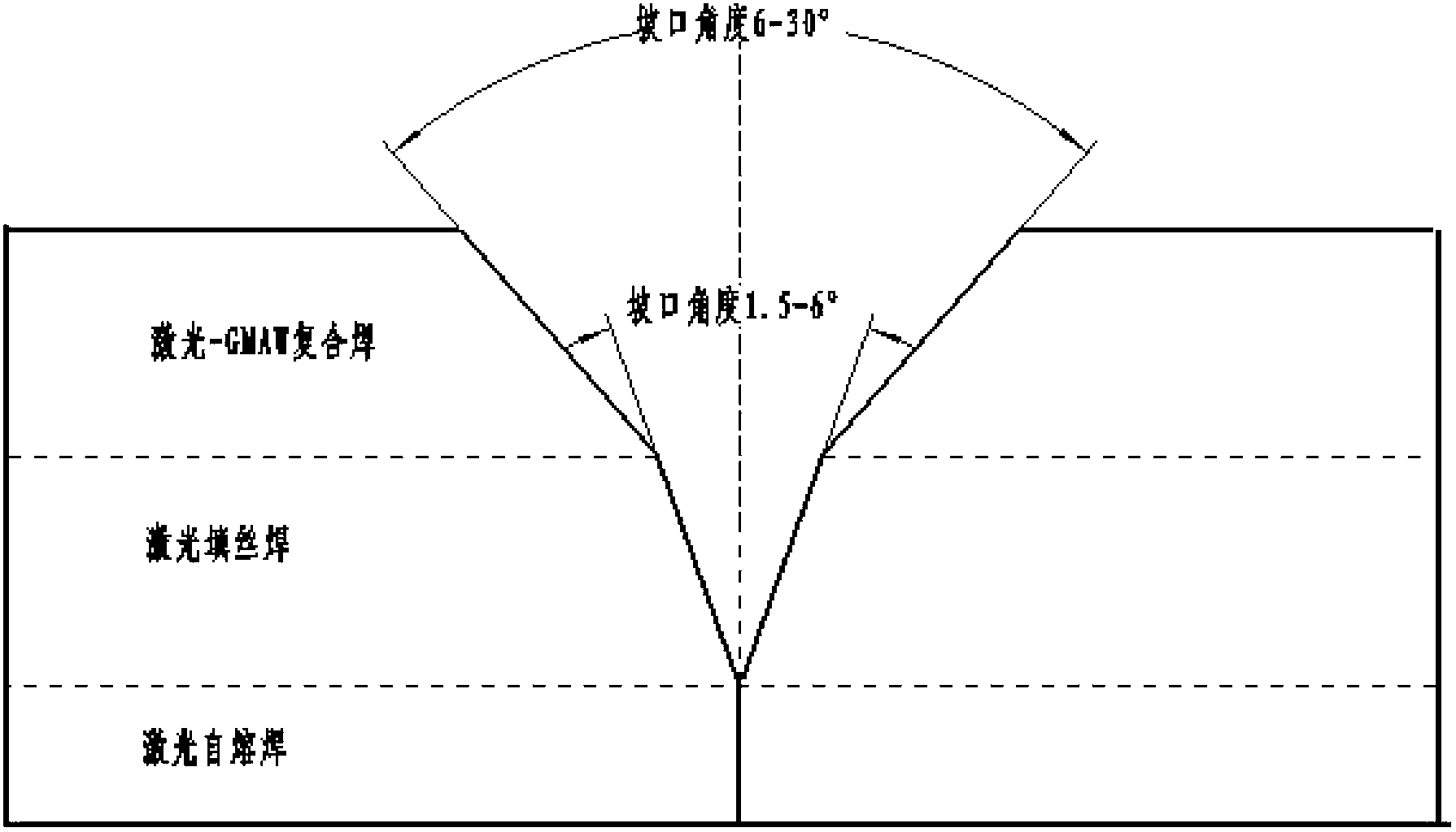
[0039] Δx=-0.35mm, the protective gas is Ar+CO 2 , air flow = 1.0m 3 / h, groove angle 1.5°

[0040] When composite welding: V welding = 0.6m / min, V delivery = 4.2m / min, I = 230A, P = 1kw,

[0041] Δf=-1mm, Δx=3mm, the protective gas is Ar+CO 2 , air flow = 1.0m 3 / h, groove angle 10°.

example 2

[0043] Welding material: marine structural steel plate (150*75*18mm 3 )

[0044] During self-fusion welding: V welding = 0.6m / min, p = 4kw

[0045] When filling wire welding: V welding = 0.5m / min, V delivery = 4.3m / min, P = 4kw, Δf = 0mm, Δx = 0mm, the shielding gas is Ar+CO 2 , air flow = 1.1m 3 / h, bevel angle 3.5°

[0046] For composite welding: V welding = 0.7m / min, V delivery = 4.4m / min, I = 240A, P = 1.5kw, Δf = 0mm, Δx = 4mm, the shielding gas is Ar+CO 2 , air flow = 1.1m 3 / h, bevel angle 15°

example 3

[0048] Welding material: marine structural steel plate (150*75*18mm 3 )

[0049] During self-fusion welding: V welding = 0.5m / min, p = 5kw

[0050] When filling wire welding: V welding = 0.6m / min, V delivery = 4.5m / min, P = 4kw, Δf = 1mm, Δx = 0.65mm, the shielding gas is Ar+CO 2 , air flow = 1.2m 3 / h, bevel angle 6°

[0051] For hybrid welding: V welding = 0.8m / min, V delivery = 4.5m / min, I = 250A, P = 2.5kw, Δf = 1mm, Δx = 5mm, the shielding gas is Ar+CO 2 , air flow = 1.2m 3 / h, groove angle 30°


PUM

PropertyMeasurementUnit
angleaaaaaaaaaa
angleaaaaaaaaaa

Abstract

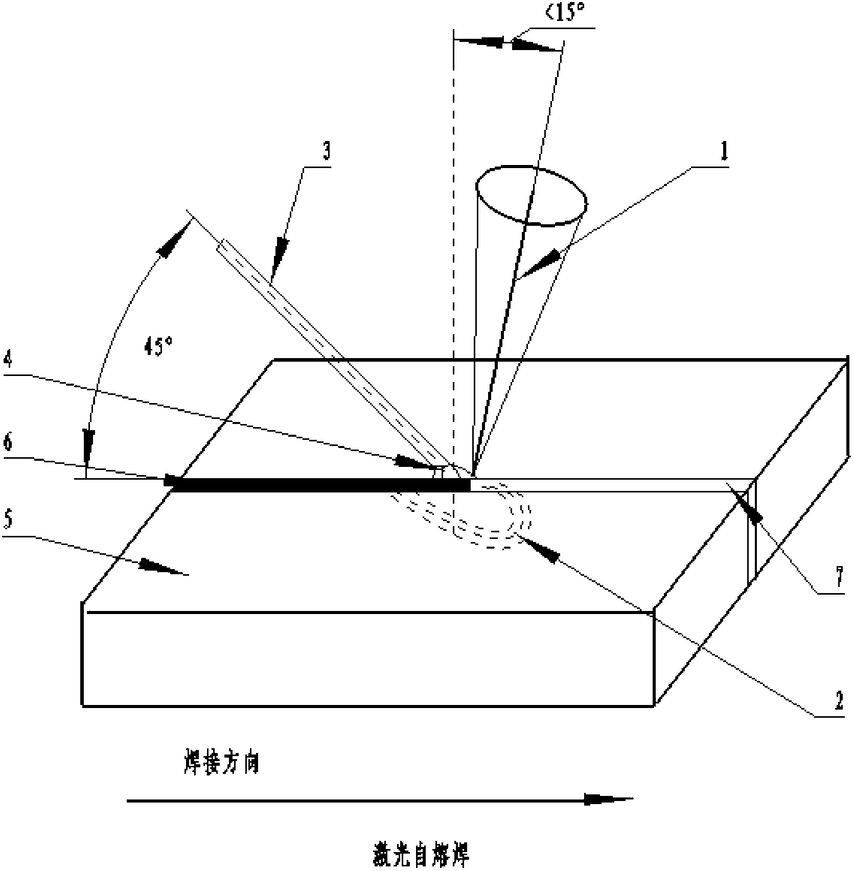
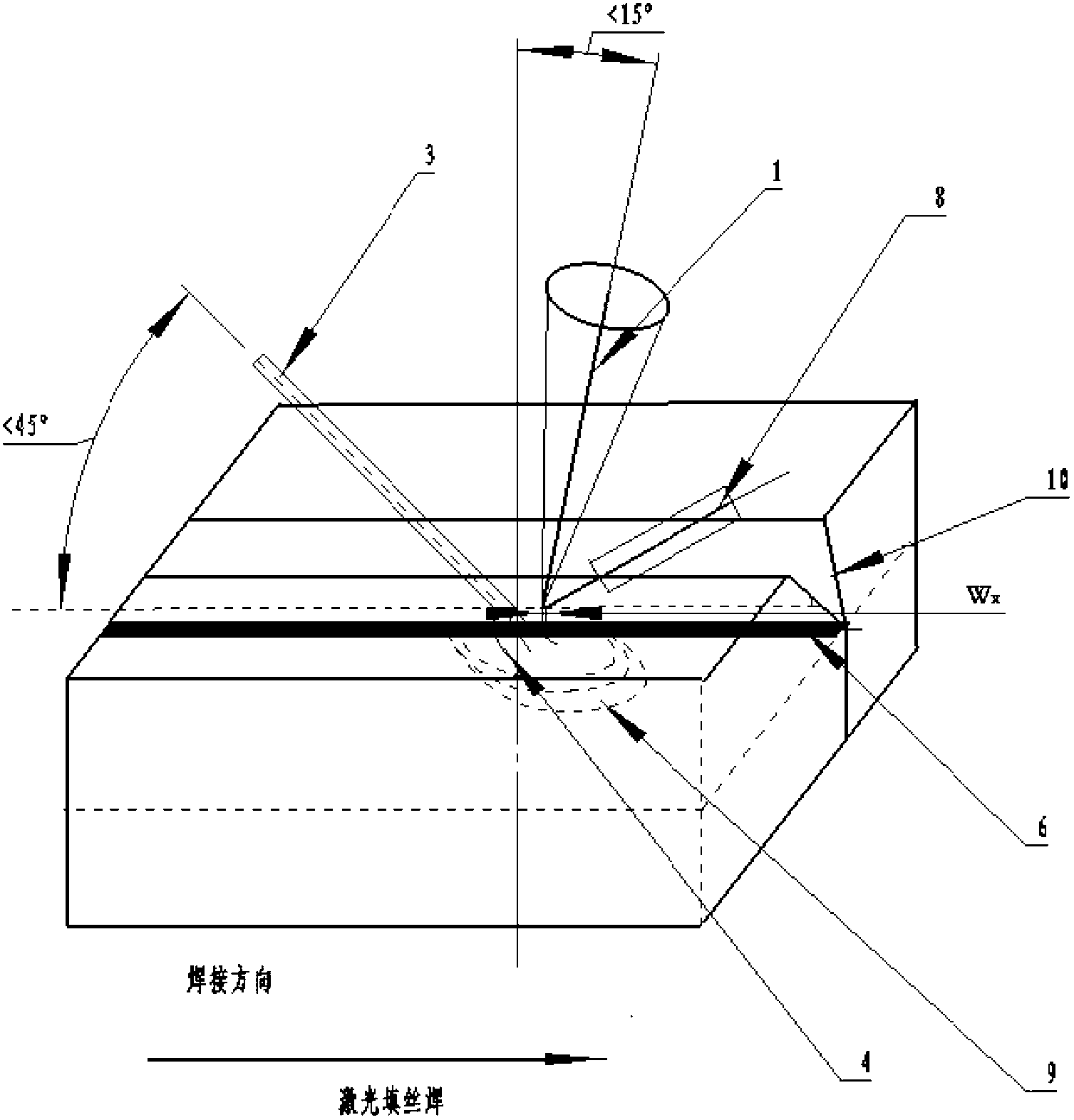
The invention discloses a laser welding method for a thick plate. A gap is reserved on the thick plate or a divided edge with a blunted edge is performed, a laser autogenous welding is adopted at the welding bead part for welding a pass for bottoming, then, the laser wire filling welding is carried out, a welding wire and a laser beam maintain an included angle being 15 degrees to 75 degrees, the welding wire extends into the divided edge gap from the front of the laser beam, when the filling wire welding cannot fully fill the divided edge gap, the laser-GMAW (gas metal arc welding) composite welding is finally carried out, and the welding of the thick plate is completed. The preserved gap value is respectively smaller than or equal to 0.5mm, the width of the performed welding bead used for the wire filling welding is smaller than or equal to 2.5mm, and the width of the performed welding bead used for the composite welding is smaller than or equal to 10mm. The laser welding method has the advantages that the problem of high-efficiency and high-quality welding of the thick plate is solved, so high-quality and efficient thick plate welding joints with small welding deformation and high gap bridging capability are obtained.

Description

technical field [0001] The invention belongs to the technical field of laser material processing, and relates to a narrow-gap multi-pass laser welding method for thick plates. The optimized combination realizes high-efficiency and high-quality welding of thick plates. Background technique [0002] The welding of thick plates is an essential key process in the manufacture of ships and nuclear facilities, the laying of oil and gas pipelines, the construction of power stations, and the construction of various large-scale steel structure projects. The thickness of these facility components is generally more than 20mm, and the structural size is large, so they can only be connected and formed after segmental processing. [0003] In view of the current welding methods, (1) when arc welding is used to weld thick plates, it is usually necessary to open a bevel and perform multi-layer and multi-pass welding. However, due to the sharp increase of the groove area, the amount of weldi...

Claims


Application Information

Patent Timeline
Patent Type & Authority Applications(China)
IPC IPC(8): B23K28/02B23K33/00B23K26/346
Inventor 王春明李若杨王天骄胡席远王军
Owner HUAZHONG UNIV OF SCI & TECH
Learn More