Tunnel pipe thin-layer retort for coal and oil shale and retort process thereof
A technology of oil shale and tunnel pipe, which is applied in the dry distillation device of shale oil to produce coal tar, which can solve the problems of difficult to control the dry distillation time accurately, large heat loss in the semi-coke cooling section, and small processing capacity of a single furnace. Reach the effect of reducing oil sludge, improving the utilization rate of raw materials, and reducing the total amount of treatment
- Summary
- Abstract
- Description
- Claims
- Application Information
AI Technical Summary
Problems solved by technology
Method used
Image
Examples
specific Embodiment approach 1
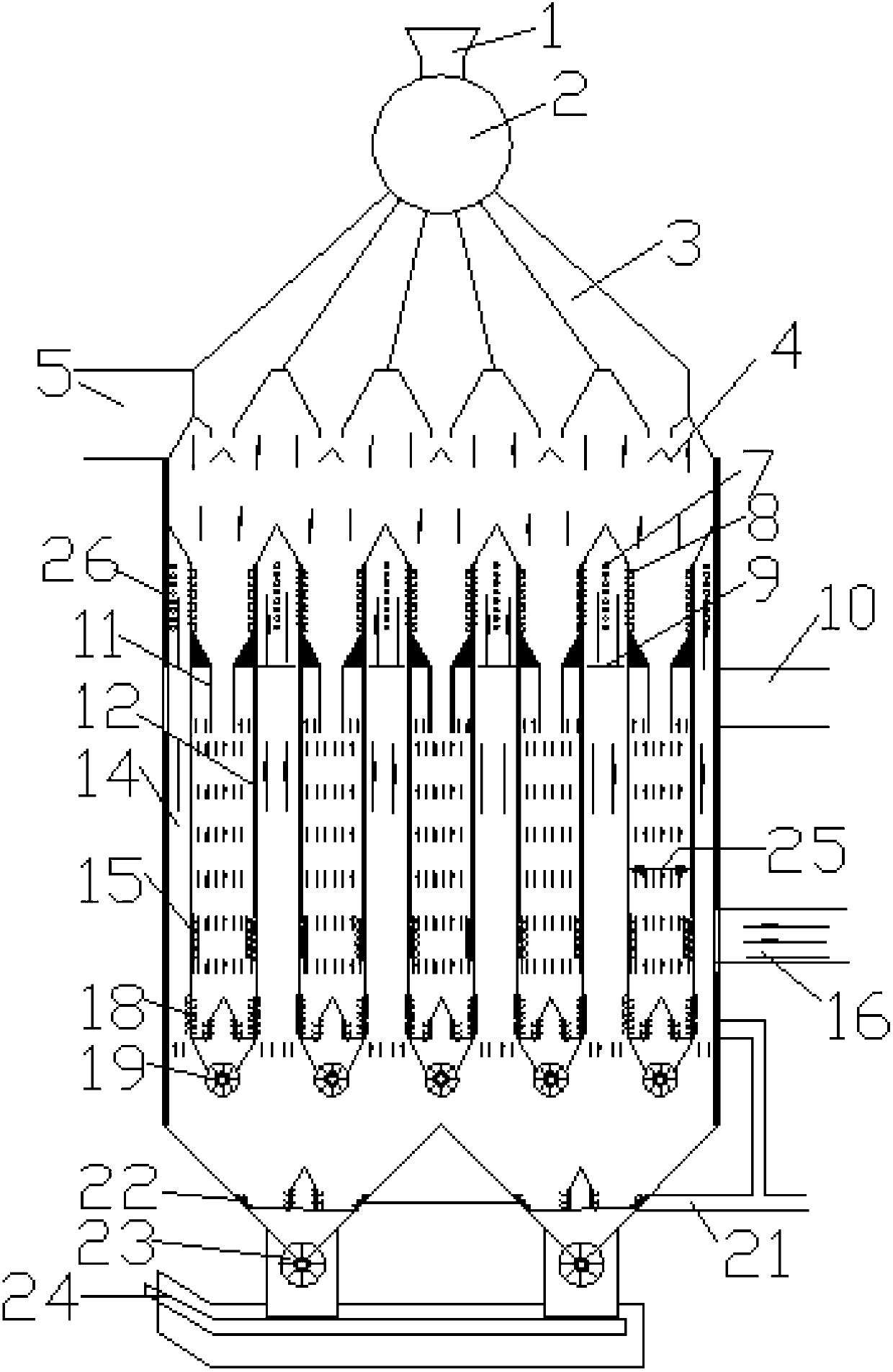
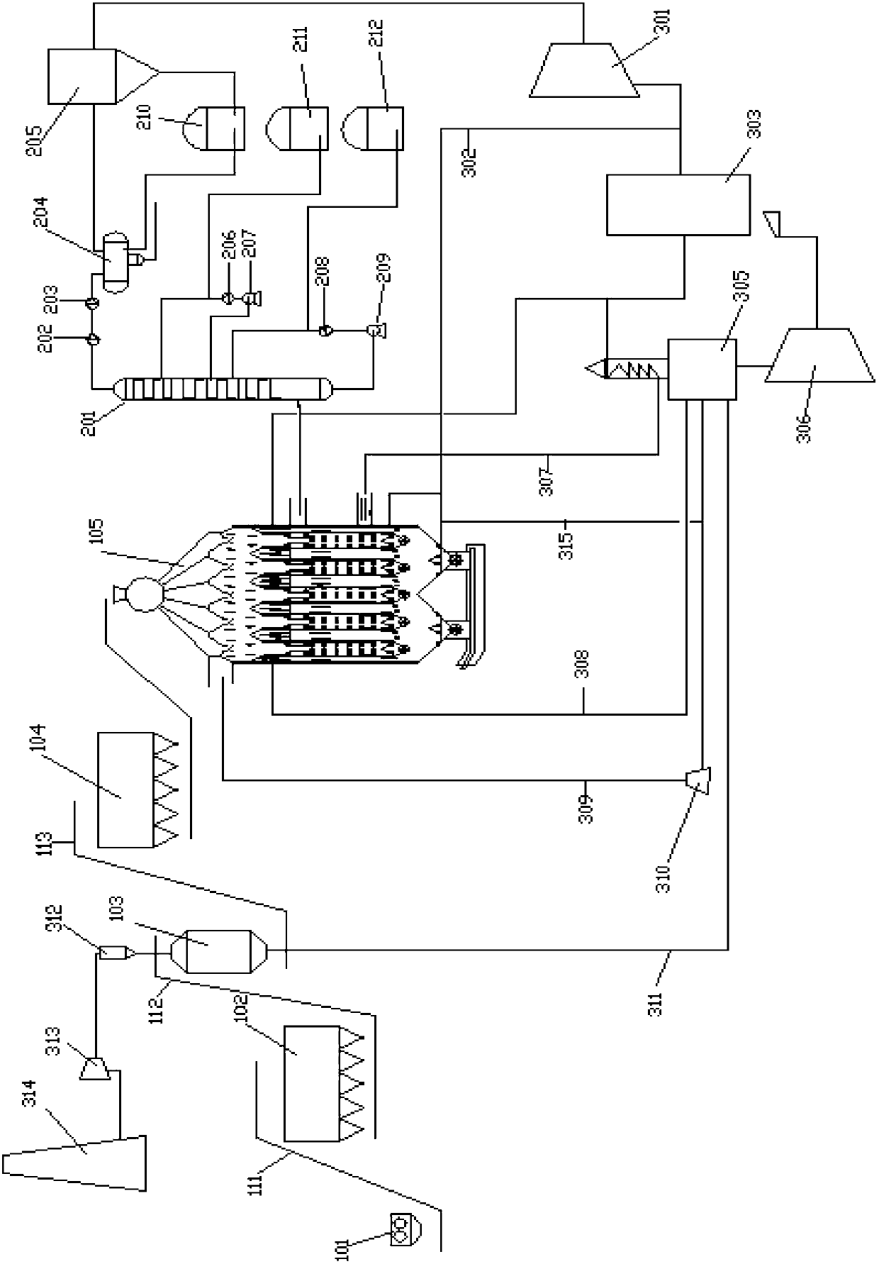
[0037] Specific implementation mode one: below in conjunction with attached figure 1 And attached figure 2 To further explain the specific implementation method:
[0038] In this embodiment, the coal and oil shale tunnel tube thin-layer dry distillation device includes a hopper 1, a gas seal 2, a material distribution mechanism 3, a herringbone baffle 4, a dry distillation gas heat exchange tube 7, an adjustment baffle 9, a feeding pipe 11, Composite wall 12, tunnel pipe 14, roller unloading machine 19, semi-coke unloading machine 23, scraper unloading machine 24, single-section retort chamber 25 and shell 26;
[0039] The top of the tunnel tube thin-layer carbonization device for coal and oil shale is a hopper 1, and the gas seal 2 is connected to the bottom. A herringbone baffle 4 is connected below, and multiple groups of single-section retort chambers 25 arranged at intervals are arranged in the middle of the retort device, and a retort gas outlet 10 is opened in the mi...
specific Embodiment approach 2
[0045] Embodiment 2: The difference between this embodiment and Embodiment 1 is that the roller blanking machine 19 is a hollow circular shaft, and the outer cylindrical surface of the shaft is evenly distributed with 3 to 8 metal plates installed along the central axis and vertical to the axial surface. The metal plates are connected to the metal reinforcing plate at an interval of 0.8 to 1.5 meters, and the space between the metal plates is a semi-coke cutting trough. Other devices and parameters are the same as those in Embodiment 1.
specific Embodiment approach 3
[0046] Embodiment 3: This embodiment differs from Embodiment 1 or Embodiment 2 in that the hollow circular shaft of the roller feeder 19 is cooled by desalted water or purified retort gas. Other devices and parameters are the same as those in Embodiment 1 or 2.
PUM
| Property | Measurement | Unit |
|---|---|---|
| thickness | aaaaa | aaaaa |
| thickness | aaaaa | aaaaa |
| thickness | aaaaa | aaaaa |
Abstract
Description
Claims
Application Information
 - R&D
- Intellectual Property
- Life Sciences
- Materials
- Tech Scout
- Unparalleled Data Quality
- Higher Quality Content
- 60% Fewer Hallucinations
Browse by: Latest US Patents, China's latest patents, Technical Efficacy Thesaurus, Application Domain, Technology Topic, Popular Technical Reports.
© 2025 PatSnap. All rights reserved.Legal|Privacy policy|Modern Slavery Act Transparency Statement|Sitemap|About US| Contact US: help@patsnap.com


