
A cam-type continuously variable transmission method and transmission

A continuously variable speed and cam-type technology, which is applied in belts/chains/gears, mechanical equipment, transmission devices, etc., can solve problems such as low load-carrying capacity, poor resistance to overload and impact resistance, and high requirements for parts processing and lubrication. Efficiently balanced speed and power output, guaranteed continuity and stability, continuous subtle stepless modulation and balanced output effect

Inactive Publication Date: 2015-10-28
周忠达
View PDF7 Cites 0 Cited by
  • Summary
  • Abstract
  • Description
  • Claims
  • Application Information

AI Technical Summary

Problems solved by technology

The main characteristics of mechanical transmission are: stable speed, small slip rate, reliable operation, constant power mechanical characteristics, high transmission efficiency, simple structure, convenient maintenance, and relatively cheap price; Low, poor overload resistance and impact resistance, so it is generally suitable for medium and small power transmission

Method used


Image

  • A cam-type continuously variable transmission method and transmission
  • A cam-type continuously variable transmission method and transmission
  • A cam-type continuously variable transmission method and transmission

Examples


Embodiment 1

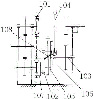
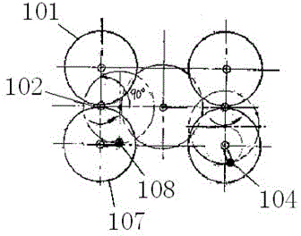
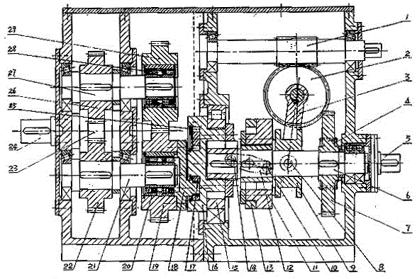
[0042] Such as Figure 1 to Figure 5 Shown is an adjustable eccentric end face circular groove cam type CVT according to the present invention, which includes a casing, an input shaft 5 is installed on the casing, a gear 4 is tightly mounted on the input shaft 5, and the gear 4 is tightly mounted on the gear The gear 7 on the main shaft 6 is meshed, and the power is transmitted to the gear main shaft 6, which is tightly mounted on the gear main shaft 6. The cam disc installation flange 15 is also tightly installed on the gear main shaft 6, and the end surface circular groove cam 16 is installed on the cam disc installation flange 15. And it can slide radially along the radial hole groove on the cam disc installation flange 15; The circular groove on the end face drives the roller 25, the finger ring 17 and the crank finger plate 18, and the crank finger plate 18 drives the ring gears 19, 29 tightly mounted on the one-way bearings (one-way overrunning clutches) 20, 28 along the...


PUM


Abstract

The invention discloses a cam type stepless speed change method and a transmission. Two groups of end face circular groove cam crank stud transmission pair are stacked together in parallel in a staggering manner, speed regulation is realized through regulating an offset of the center of an end face disc cam to the center of a primary gear main shaft, a control mechanism is operated to correct and filter the speed regulation and speed change of a speed change mechanism with an end face circular groove cam, the disadvantage operation speeds of an upper starting point and a lower starting point of the end face circular groove cam crank stud transmission pair and adjacent low velocity low efficiency operating areas are eliminated, the advantage operating speeds of high speed high efficiency areas are reserved, so that the efficient balanced variable transmission of the transmission is realized, when the speed is regulated and changed, the inertia moment of a balancing mechanism is synchronously regulated, and the mechanical vibration which is generated by offset variation is eliminated; and finally, the power is output through the speed collection of a crank gear ring pair with a unidirectional bearing.

Description

technical field [0001] The present invention relates to a mechanical transmission mode and device, especially a continuously variable transmission mode and device; it is mainly used in automobiles, rolling stock, ships, construction machinery, agricultural machinery, mining machinery, light textile machinery and aerospace machinery Equipped with continuously variable speed. Background technique [0002] In the current mechanical engineering, speed change is a mechanical transmission method that is often used. The speed change is mainly realized through the transmission; gearboxes and continuously variable transmissions. [0003] With the continuous improvement of technology, continuously variable transmission is more and more widely used; the so-called continuously variable transmission refers to a transmission system that can continuously obtain any transmission ratio within the transmission range. The best match between the drive train and the engine operating conditions...

Claims


Application Information

Patent Timeline
Patent Type & Authority Patents(China)
IPC IPC(8): F16H37/12
Inventor 周忠达周文杰
Owner 周忠达
Learn More