Multi-channel integrating light guide mode multiplexing-demultiplexing device

An integrated optical waveguide and mode multiplexing technology, applied in the field of multiplexing-demultiplexing, can solve the problems of inconvenient design, complex design, and fewer channels, and achieve the effect of convenient design, compact structure, and easy expansion

Active Publication Date: 2013-04-03
ZHEJIANG UNIV
View PDF3 Cites 31 Cited by
  • Summary
  • Abstract
  • Description
  • Claims
  • Application Information

AI Technical Summary

Problems solved by technology

The literature [Maxim Greenberg et al., "Simultaneous dual mode add / drop multiplexers for optical interconnects buses," Optics Communications 266 (2006) 527–531] designed a dual-mode add / drop multiplexer based on the principle of adiabatic power transfer It can upload / download two modes at the same time, but its design is complicated, it is not easy to expand, and it only works on a single polarization
Literature 【S. Bagheri, and William M. J. Green “Silicon-on-insulator mode-selective add-drop unit for on-chip mode-division multiplexing,” 6th IEEE International Conference on Group IV Photonics, 2009 (GFP '09), Page (s): 166-168, 9-11 Sept. 2009】Given a dual-mode add-drop multiplexer based on multi-level mode coupling, but only realized the multiplexing of the fundamental mode and the first high-order mode, its structure Mode multiplexing that is complex, inconvenient to design, large device size, and not easily scalable to more channels
In conclusion, there are still few researches on mode (de)multiplexing technology, especially integrated optical waveguide mode multiplexer-demultiplexer for on-chip optical interconnection system, and there are few reported mode (de)multiplexers. ) The multiplexer only works on a single polarization, with few channels and poor scalability, making it difficult to meet the needs of large-capacity and multi-channel

Method used


Image

  • Multi-channel integrating light guide mode multiplexing-demultiplexing device
  • Multi-channel integrating light guide mode multiplexing-demultiplexing device

Examples


Embodiment Construction

[0019] The present invention will be further described below in conjunction with drawings and embodiments.

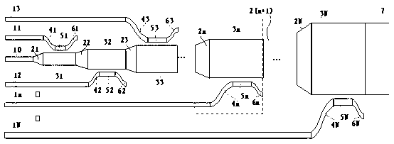
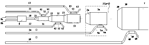
[0020] Such as figure 1 As shown, N+1 input optical waveguides 10, 11, 12, ..., 1n, ..., 1N are single-mode optical waveguides for receiving the light, N>0; where:

[0021] The end of the 0th input optical waveguide 10 is sequentially connected with the first tapered optical waveguide 21, the first multimode optical waveguide 31, the second tapered optical waveguide 22, the second multimode optical waveguide 32, ..., the nth tapered optical waveguide 2n, the nth multimode optical waveguide 3n, ..., the Nth tapered optical waveguide 2N, the Nth multimode optical waveguide 3N, the output multimode optical waveguide 7;

[0022] The nth input waveguide 1n, where n=1,...,N, the ends of each input optical waveguide are sequentially connected with an S-shaped curved optical waveguide structure 4n, a coupling region optical waveguide 5n and another S-shaped curved optical wave...


PUM


Abstract

The invention discloses a multi-channel integrating light guide mode multiplexing-demultiplexing device. The multi-channel integrating light guide mode multiplexing-demultiplexing device comprises (N+1) input monomode optical waveguides (N is greater than 0), wherein the tail end of the zero input light guide is successively connected with a first cone light guide, a first multimode optical waveguide, an nth cone light guide, an nth multimode optical waveguide,......, the nth cone light guide, the nth multimode optical waveguide, and an output multimode optical waveguide as well as an nth input waveguide, n=1,......, N, each input light guide tail end is successively respectively connected with a S-shaped winding light guide, a coupled zone light guide and the other S-shaped winding light guide structure; and the nth high-order mode of the nth multimode optical waveguide is a transverse electric mode or a transverse magnetic mode, and n=1,......, N. The multi-channel integrating light guide mode multiplexing-demultiplexing device provided by the invention can respectively load multi-path signals on N eigen modes of the same multimode waveguide, the model multiplexing is formed, and the large capacity data transmission is realized; and the multi-channel integrating light guide mode multiplexing-demultiplexing device is suitable for a key function device of a dual-polarization mode multiplexing system, the design is convenient, the structure is compact, and the expansion is convenient.

Description

technical field [0001] The invention relates to a multiplexer-demultiplexer, in particular to a multi-channel integrated optical waveguide mode multiplexer-demultiplexer for a mode multiplex system. Background technique [0002] As we all know, long-distance optical communication has achieved great success. Similarly, optical interconnection, as a new interconnection method, can overcome the bottleneck problem of traditional electrical interconnection, and has attracted widespread attention. Since J. W. Goodman proposed to adopt the optical interconnection scheme in VLSI in 1984, the research of optical interconnection has made great progress. At present, optical interconnection is continuously advancing towards ultra-short distance interconnection, and its communication capacity demand is increasing day by day. In view of the large amount of data transmission in the optical interconnection system, the most direct method is to borrow the wavelength division multiplexing (W...

Claims


Application Information

Patent Timeline
Patent Type & Authority Applications(China)
IPC IPC(8): H04J14/04H04J14/06
Inventor 戴道锌
Owner ZHEJIANG UNIV
Why Eureka
Try Eureka