
Quantitative PCR (polymerase chain reaction) detection system for tunable fluorescent

A detection system and fluorescence quantitative technology, applied in the direction of fluorescence/phosphorescence, material excitation analysis, etc., can solve the problems of optical fiber affecting the stability of the optical path, long experiment time, high cost, and achieve a simple and reliable optical path system, improved detection efficiency, and fewer moving parts. Effect

Inactive Publication Date: 2013-04-10
XIAMEN UNIV
View PDF9 Cites 11 Cited by
  • Summary
  • Abstract
  • Description
  • Claims
  • Application Information

AI Technical Summary

Problems solved by technology

[0004] 1) The fluorescence detection module is not fixed, and the motor drives the fiber optic probe to move. While scanning, the vibration of the fiber will affect the stability of the optical path, thereby affecting the detection accuracy
[0005] 2) The scanning part of the instrument has complex mechanical structure, high cost and high quality. The scanning probe is driven by the motor to scan in the X and Y directions, requiring two motors to work together, which is not conducive to miniaturization
There are also Chinese patents 200680019254.1 and 200410066294.4 similarly, but the common feature of the above three patents is that they can only perform multi-wavelength fluorescence detection methods on the same tube of samples, and cannot perform real-time fluorescence detection on all samples on the orifice plate at the same time.
To obtain the fluorescence signals of all samples, the movement of the detection device must be controlled. This detection method requires a long experiment time, low efficiency, complex mechanical structure and high cost.

Method used


Image

  • Quantitative PCR (polymerase chain reaction) detection system for tunable fluorescent

Examples


Embodiment Construction

[0018] The present invention will be further described below in conjunction with accompanying drawing.

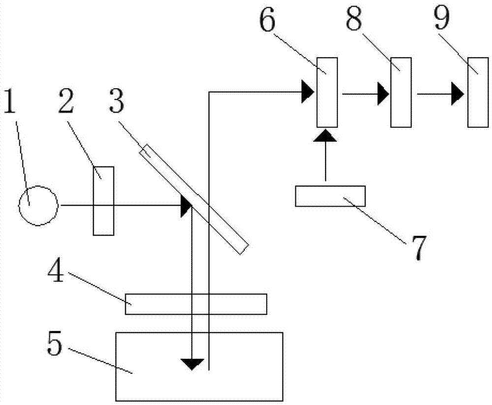
[0019] see figure 1 , the embodiment of the present invention is provided with a light source 1, an excitation filter 2, a dichroic mirror 3, a lens group 4, a thermal cycle system 5, a tunable filter 6, a tuning control unit 7, an area array detector 8 and information Analysis processing unit 9;

[0020] The light source 1 and the excitation filter 2 are arranged on the horizontal axis of the dichroic mirror 3 at 45° to the horizontal direction, and the light emitted by the light source 1 enters the dichroic mirror through the excitation filter 2 3; the lens group 4 and the thermal cycle system 5 are arranged on the vertical axis of the dichroic mirror 3, and the excitation light enters the thermal cycle system 5 through the lens group 4; the tunable filter 6 is arranged on the on the horizontal axis or the vertical axis of the dichroic mirror 3; the center of the area a...


PUM

PropertyMeasurementUnit
Wavelength rangeaaaaaaaaaa

Abstract

The invention discloses a quantitative PCR (polymerase chain reaction) detection system for tunable fluorescent, and relates to a PCR detection system. The tunable quantitative fluorescent PCR detection system is provided with a light source, an excitation light filter, a dichroscope, a lens group, a thermal cycling system, a tunable light filter, a tuning control unit, an area-array detector and an information analyzing and processing unit; the light source and the excitation light filter are arranged on the horizontal axis (which forms a 45-degree angle with the horizontal direction) of the dichroscope, and light emitted by the light source is irradiated on the dichroscope through the excitation light filter; the lens group and the thermal cycling system are arranged on the vertical axis of the dichroscope, and excitation light is irradiated on the thermal cycling system through the lens group; the tunable light filter is arranged on the horizontal axis or the vertical axis of the dichroscope; the centre of the area-array detector and the centre of the tunable light filter are located on a same straight line; the tuning control unit is used for controlling the rotation of the tunable light filter; and the area-array detector is connected with the information analyzing and processing unit. The quantitative PCR detection system for the tunable fluorescent is simple in structure, easy and convenient to operate, and capable of performing multi-wavelength fluorescent detection imaging on all samples.

Description

technical field [0001] The invention relates to a PCR detection system, in particular to a tunable fluorescent quantitative PCR detection system capable of collecting the excited fluorescent signals of different fluorescent dyes. Background technique [0002] Fluorescent quantitative PCR detection system is an instrument that automatically cycles the reactant between the specified denaturation temperature, annealing temperature and extension temperature. Through the temperature cycle of denaturation, annealing and extension, the target DNA can be amplified hundreds of times in a short time. ten thousand times. At the same time, by irradiating the test tube with different wavelengths of excitation light, when the reagent in the test tube is excited to fluoresce, the optical sensor (PMT, PD, CCD, etc.) collects the fluorescence intensity signal and transmits it to the computer for real-time data display and analysis. [0003] Traditional fluorescent quantitative PCR instrumen...

Claims


Application Information

Patent Timeline
IPC IPC(8): G01N21/64
Inventor 陈延平李纯彬马雄
Owner XIAMEN UNIV
Learn More