Magnetic separator
A magnetic separator and magnetic separation technology, applied in the field of magnetic separators, can solve the problems that the magnetic energy of the magnetic system cannot be fully utilized, the magnetic field strength of the outer wall of the drum is weakened, and the physical inclusions of the magnetic separation concentrate are large, so as to improve the utilization rate of magnetic energy, Small footprint and wide magnetic separation area
- Summary
- Abstract
- Description
- Claims
- Application Information
AI Technical Summary
Problems solved by technology
Method used
Image

Examples
Embodiment Construction
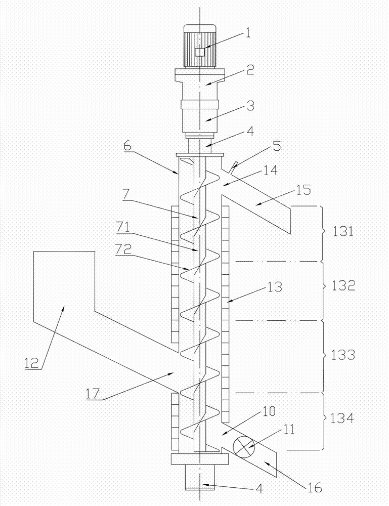
[0023] The present invention will be described in further detail below in conjunction with the accompanying drawings and specific embodiments.
[0024] Such as figure 1 As shown, the magnetic separator of the present invention includes a beneficiation chamber 6 for ore pulp to pass through, a magnetic separation assembly 13 is fixed on the outer wall of the beneficiation chamber 6, and a magnetic separation assembly 13 is fixed on the outer wall of the beneficiation chamber 6. The magnetic material is pushed out of the pushing part 7 of the beneficiation chamber 6 . After the pulp enters the beneficiation chamber 6, the magnetic materials in it are captured by the magnetic force of the magnetic separation assembly 13, forming a material layer with a certain thickness on the inner wall of the beneficiation chamber 6, and pushed out of the beneficiation chamber 6 by the pushing member 7.
[0025] In this embodiment, the pushing member 7 includes a rotating shaft 71 pierced in t...
PUM
 Abstract
Description
Claims
Application Information
 - Generate Ideas
- Intellectual Property
- Life Sciences
- Materials
- Tech Scout
- Unparalleled Data Quality
- Higher Quality Content
- 60% Fewer Hallucinations
Browse by: Latest US Patents, China's latest patents, Technical Efficacy Thesaurus, Application Domain, Technology Topic, Popular Technical Reports.
© 2025 PatSnap. All rights reserved.Legal|Privacy policy|Modern Slavery Act Transparency Statement|Sitemap|About US| Contact US: help@patsnap.com