
Pyrolysis and gasification method and device for preparing tar-free hydrogen-rich gas

A pyrolysis gasification, tar-free technology, used in the manufacture of combustible gas, petroleum industry, etc., can solve problems such as agglomeration and affecting the normal operation of the process

Active Publication Date: 2013-04-17
INST OF PROCESS ENG CHINESE ACAD OF SCI
View PDF8 Cites 17 Cited by
  • Summary
  • Abstract
  • Description
  • Claims
  • Application Information

AI Technical Summary

Problems solved by technology

However, the process is carried out under high pressure conditions, and the carbon dioxide absorbent KOH or Ca(OH) 2 Serious agglomeration affects the normal operation of the process
At the same time, the tar generation and its treatment methods in the whole process are not mentioned

Method used


Image

  • Pyrolysis and gasification method and device for preparing tar-free hydrogen-rich gas
  • Pyrolysis and gasification method and device for preparing tar-free hydrogen-rich gas
  • Pyrolysis and gasification method and device for preparing tar-free hydrogen-rich gas

Examples


preparation example Construction

[0043] The pyrolysis gasification method for preparing tar-free hydrogen-rich gas of the present invention comprises the following steps:

[0044] 1) The carbon-containing solid raw material is sent into the upstream pyrolysis reactor through the feeding device for pyrolysis to produce pyrolysis gas phase products and solid products;

[0045] 2) The pyrolysis gas phase products and solid products produced in step 1) are passed into the downstream tar cracking reactor, and the tar is removed through high-temperature pyrolysis, partial oxidation and pyrolysis semi-coke catalytic cracking reactions to obtain pyrolysis gas and pyrolysis semi-coke. coke.

[0046] The upstream pyrolysis reactor can be a rotary kiln, a fluidized bed or a dilute phase transport bed. The above-mentioned downstream tar cracking reactor can be a rotary kiln, a dilute phase conveying bed, a settling furnace or a fixed bed.

[0047] The carbon-containing solid raw material is coal, biomass or other carbon-...

Embodiment 1

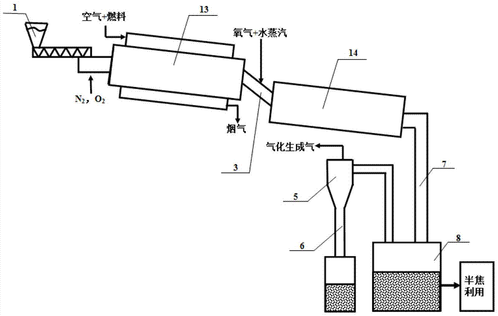
[0058] The schematic diagram of the pyrolysis gasification device combined with the two-stage rotary kiln reactor in this embodiment is as follows figure 2 As shown, it includes a feeding device 1, a first rotary kiln reactor 13, a second rotary kiln reactor 14, a coke quenching device 8, a cyclone separator 5, a dipleg 6, and the like.

[0059] When using this pyrolysis gasification device to prepare tar-free hydrogen-rich gas, carbon-containing solid fuel (such as coal) with a particle size of <20mm is sent to the upstream first rotary kiln through the feeding device 1 (such as a screw feeder) Pyrolysis is carried out at 700-900°C in the reactor 13, and the generated mixed gas and solid products enter the downstream second rotary kiln reactor 14 through the overflow pipe 3. A certain amount of oxygen, water vapor and other gases are introduced into the second rotary kiln reactor 14 and maintained at 1100°C. In the second rotary kiln reactor 14, the thermal cracking and par...

Embodiment 2

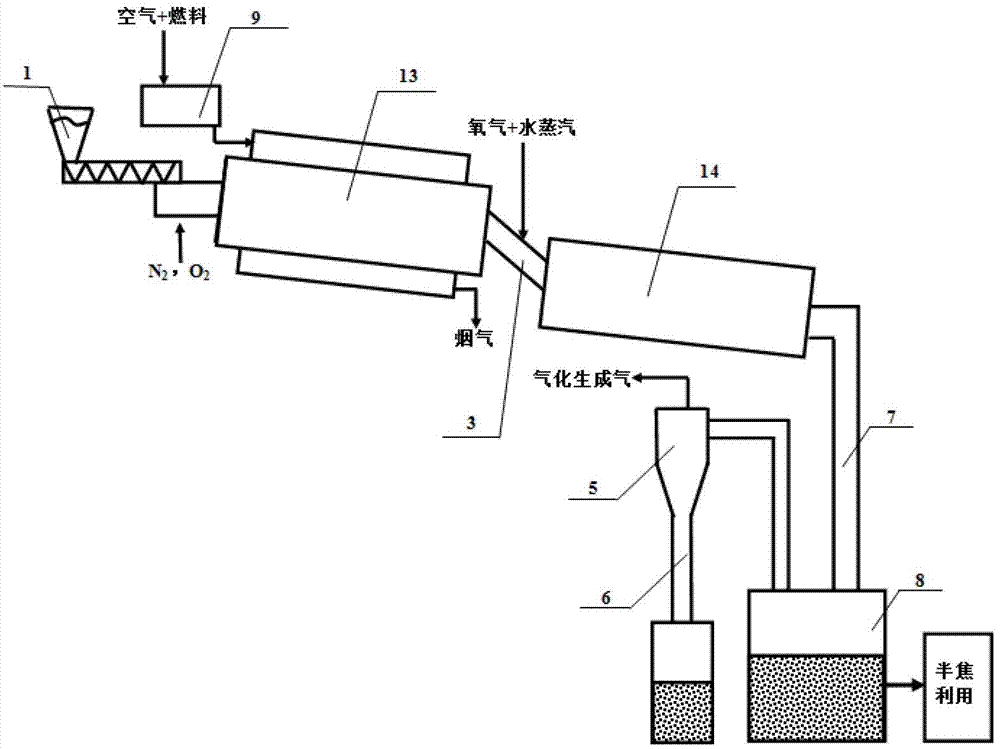
[0062] The schematic diagram of the pyrolysis gasification device of this embodiment is as follows image 3 As shown, in this embodiment, a burner 9 is added outside the upstream first rotary kiln reactor 13 described in embodiment 1, and hot flue gas is used as the heat source of the first rotary kiln reactor 13, and the others are the same as in embodiment 1. .


PUM

PropertyMeasurementUnit
particle diameteraaaaaaaaaa

Abstract

The invention relates to the technical field of solid fuel energy and chemical industry, in particular to a pyrolysis and gasification method and device for preparing tar-free hydrogen-rich gas. The pyrolysis and gasification method for preparing the tar-free hydrogen-rich gas includes steps as follows: (1) feeding a carbonic solid raw material through a feed device to an upstream pyrolysis reactor for aerobic pyrolysis, and generating a pyrolysis gas-phase product and a solid product; and (2) feeding the pyrolysis gas-phase product and the solid product generated in the step (1) into a downstream tar pyrolysis reactor, and removing the tar through high temperature pyrolysis, partial oxidation and pyrolysis char catalytic pyrolysis reactions; and simultaneously, pyrolysis char performing partial gasification to obtain pyrolysis gas and the pyrolysis char. The method and device avoid the problem in the prior art that fuel burns to provide heat when burns volatile matters together, and causes the problems of low content of H2 and CH4 in the pyrolysis gas, large capacity for follow-up gas composition reforming reactions and the like.

Description

technical field [0001] The invention relates to the technical field of solid fuel energy chemical industry, in particular, the invention relates to a pyrolysis gasification method and a pyrolysis gasification device for preparing tar-free hydrogen-rich gas. Background technique [0002] The gasification of carbon-containing solid fuels (coal, biomass and other carbon-containing solid wastes, etc.) is an important way in the process of its utilization. At present, the gasification process in industrial operation generally adopts the autothermal method, that is, the heat required in the gasification reaction process is provided by burning part of the gasification raw materials. Due to the high reaction temperature in the whole gasification process, it is necessary to burn more than 40% of carbon-containing raw materials to maintain the temperature required for the reaction (above 1000°C). In this process, not only part of the gasification raw material is burned, but also the ...

Claims


Application Information

Patent Timeline
Patent Type & Authority Applications(China)
IPC IPC(8): C10J3/60C10J3/62C10J3/66C10J3/00C10J3/84C10J3/72
Inventor 许光文韩江则曾玺高士秋董鹏伟
Owner INST OF PROCESS ENG CHINESE ACAD OF SCI
Learn More