Magnetic ore separation equipment and method

A mineral sorting and magnetic technology, applied in the fields of magnetic separation, chemical instruments and methods, flotation, etc., can solve the problems of magnetite beneficiation magnetic inclusions, complex sorting methods, low sorting effect, etc., and achieve enhanced mineralization. effect, improve the probability of impurity selection, and improve the effect of sorting

Inactive Publication Date: 2013-04-24
沈阳华大科技有限公司
View PDF3 Cites 17 Cited by
  • Summary
  • Abstract
  • Description
  • Claims
  • Application Information

AI Technical Summary

Problems solved by technology

[0004] The purpose of the present invention is to provide magnetic mineral column sorting equipment and a sorting method to solve the magnetic inclusions in magnetite ore dressing in the prior art, the sorting method is complica

Method used


Image

  • Magnetic ore separation equipment and method
  • Magnetic ore separation equipment and method
  • Magnetic ore separation equipment and method

Examples


Embodiment 1

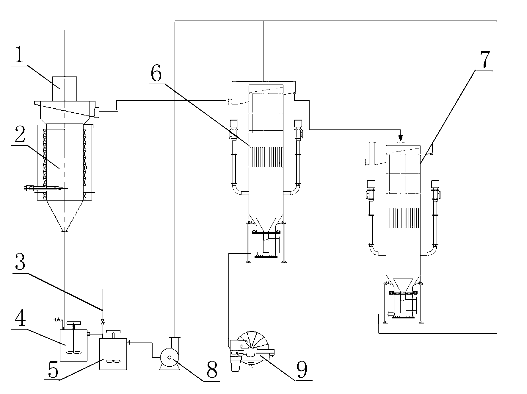
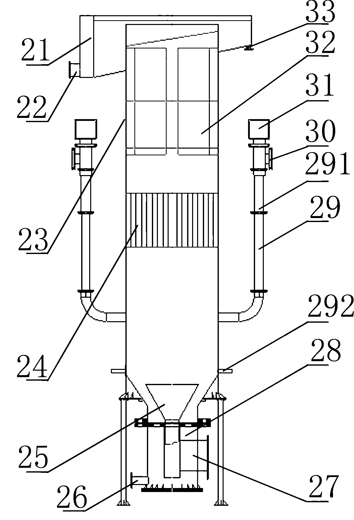
[0029] refer to figure 1 , image 3 , Figure 4 , Figure 5 , Figure 6 , Figure 8 The shown magnetic mineral separation equipment comprises a magnetic separation column 2, a first-stage magnetic flotation column 6, a second-stage magnetic flotation column 7, a first stirring tank 4, a second stirring tank 5, and the underflow ore-discharging pipe of the magnetic separation column and The ore feeding port of the first mixing tank 4 is connected, the overflow tank discharge pipe of the magnetic separation column is connected with the overflow tank of the second-stage magnetic flotation column, the ore discharge pipe of the first mixing tank is connected with the ore feeding of the second mixing tank 5 The ore discharge pipe of the second mixing tank 5 is connected with the ore feeding hopper of the first-stage magnetic flotation column, and the ore discharge pipe of the overflow tank of the first-stage magnetic flotation column is connected with the ore feeding port of the...

Embodiment 2

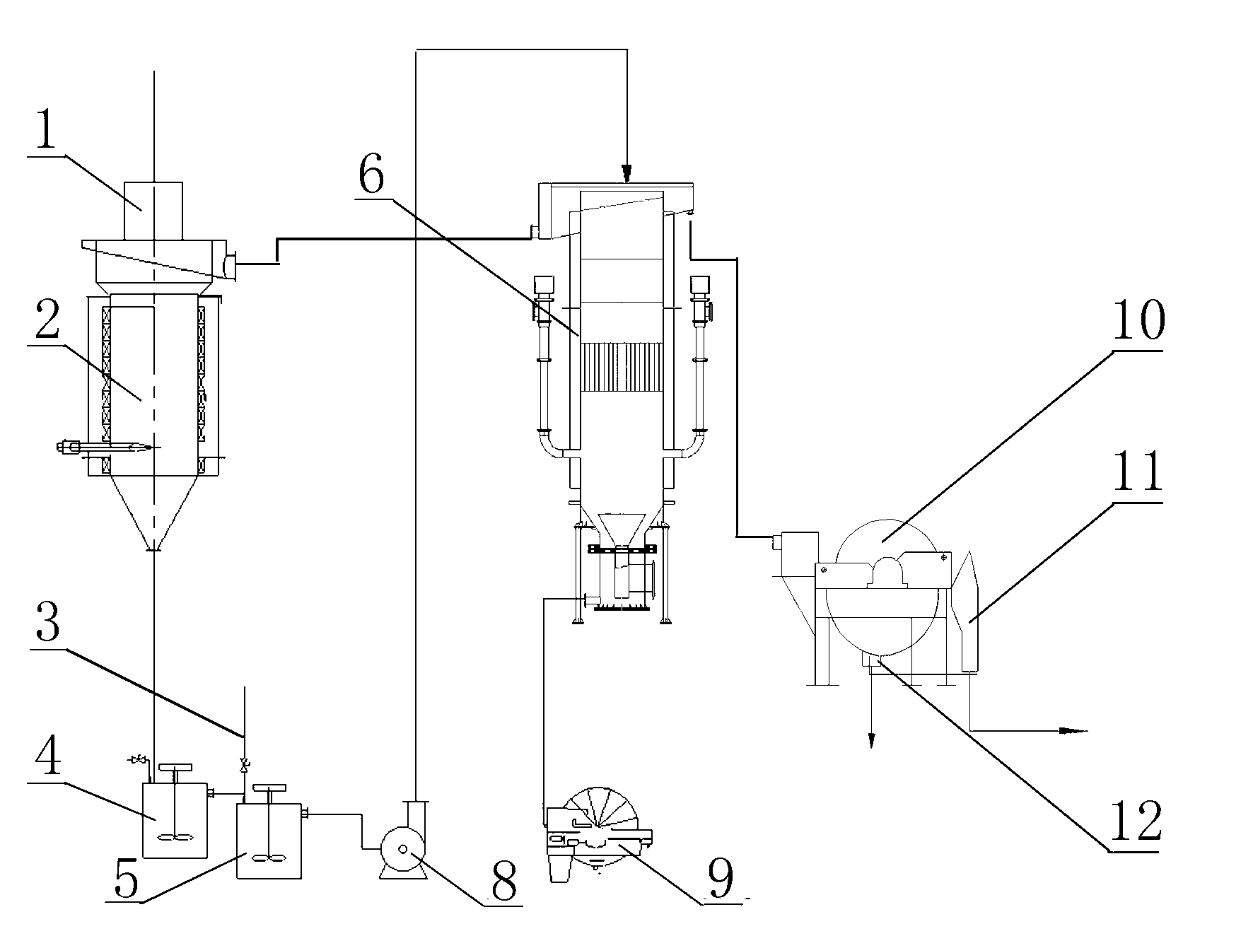
[0033] refer to figure 2 , Figure 4 , Figure 5 , Figure 6 , Figure 7 , Figure 9 The shown magnetic mineral separation equipment comprises a magnetic separation column 2, a magnetic flotation column 6, a magnetic separator 10, a first stirring tank 4, a second stirring tank 5, the bottom flow ore discharge pipe of the magnetic separation column and the first The ore feeding port of the mixing tank 4 is connected, the ore discharge pipe of the overflow tank of the magnetic separation column is connected with the overflow tank of the second-stage magnetic flotation column, and the ore discharge pipe of the first mixing tank is connected with the ore feeding port of the second mixing tank 5 , the ore discharge pipe of the second mixing tank 5 is connected to the ore feeding hopper of one section of magnetic flotation column, and the overflow tank discharge pipe of one section of magnetic flotation column is connected to the ore feeding port of magnetic separator; the tai...


PUM

PropertyMeasurementUnit
Magnetic field strengthaaaaaaaaaa

Abstract

The invention discloses magnetic ore separation equipment. According to the technical point, an underflow ore discharge pipe of a magnetic separation column is connected with a feed port of a first agitating vessel, and an overflow groove ore discharge pipe of the magnetic separation column is connected with an overflow groove of a two-section magnetism flotation column; the ore discharge pipe of the first agitating vessel is connected with the feed port of a second agitating vessel, the ore discharge pipe of the second agitating vessel is connected with a feed hopper with a one-section magnetism flotation column, the one-section magnetism flotation column is connected with a scavenging device, and the overflow groove ore discharge pipe of the one-section magnetism flotation column is connected with the feeding end of the scavenging device; the two-section magnetism flotation column or a magnetic separator is used as the scavenging device, and the underflow ore discharge pipe of the two-section magnetism flotation column is connected with the feed hopper of the one-section magnetism flotation column; and the overflow groove ore discharge pipe of the two-section magnetism flotation column or a tailings discharge pipe of the magnetic separator is connected with a tailings recovery system. The invention simultaneously provides a separation method for using the equipment. Problems in the prior art that magnetic inclusion generates in the core separation of magnetite, the separation method is complicated, the floor area is large, the separation flow path is low and the separation cost is high and the like are solved.

Description

technical field [0001] The invention belongs to the technical field of mineral separation, and relates to short-flow mineral separation equipment and a separation method, in particular to magnetic mineral column separation equipment and a method. Background technique [0002] Iron is the most commonly used metal in the world, accounting for more than 95% of total metal consumption. Due to the large-scale development of iron ore resources in my country, there is an increasing shortage of easy-to-select magnetite resources, so deep mining is required, and mining costs are gradually increasing. At present, magnetite beneficiation usually adopts continuous multi-stage magnetic separation device for separation, and finally becomes iron concentrate powder after being separated by magnetic separation column. There are also a few concentrators that use reverse flotation to separate iron concentrate powder. The flotation process has a large number of sorting stages and is complex in...

Claims


Application Information

Patent Timeline
IPC IPC(8): B03C1/30B03D1/14
Inventor 杨兴满
Owner 沈阳华大科技有限公司
Why Eureka
Try Eureka