Method for forming aluminum silicon carbide substrate for high-power module

An aluminum silicon carbide-based and silicon carbide-based technology is applied in the field of forming aluminum silicon carbide substrates, which can solve the problems of high processing costs, difficulties in preparing aluminum silicon carbide substrates, and low forming costs, and achieve improved compactness, low expansion, and The effect of high thermal conductivity

Active Publication Date: 2015-06-17
江苏时代华宜电子科技有限公司
View PDF6 Cites 0 Cited by
  • Summary
  • Abstract
  • Description
  • Claims
  • Application Information

AI Technical Summary

Problems solved by technology

[0005] Aiming at the disadvantages of difficulty in preparing aluminum silicon carbide substrates and high processing costs in the above-mentioned existing production technology, the applicant provides a method for forming aluminum silicon carbide substrates for high-power modules. This method belongs to the precision forming technology, and the forming cost is low. No material and waste of energy

Method used


Image

  • Method for forming aluminum silicon carbide substrate for high-power module
  • Method for forming aluminum silicon carbide substrate for high-power module
  • Method for forming aluminum silicon carbide substrate for high-power module

Examples


Embodiment 1

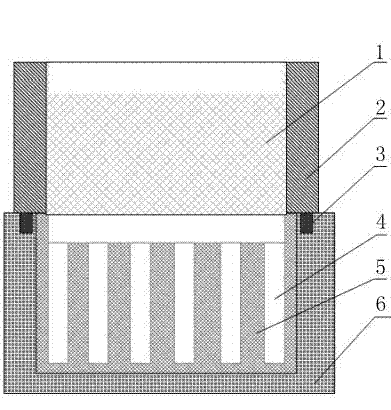
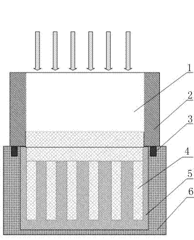
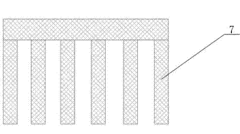
[0036] Use investment casting technology to prepare a mold shell 5 for aluminum silicon carbide substrates of a certain shape, put silicon carbide powder into the mold shell 5, compact the silicon carbide powder through two-dimensional mechanical vibration, and preheat the mold shell 5 to 800 After ℃, the aluminum alloy melt 1 is poured in, filled and solidified under hydraulic pressure, and the mold shell 5 is removed to obtain the aluminum silicon carbide substrate 7 . The surface roughness and appearance dimensions of the prepared aluminum silicon carbide substrate 7 were measured, and the surface roughness was Ra1.6, and the size deviation was ±0.05mm.

Embodiment 2

[0038] Use the shell casting technology to prepare a mold shell 5 for aluminum silicon carbide substrates of a certain shape, put the silicon carbide powder into the mold shell 5, compact the silicon carbide powder through three-dimensional mechanical vibration, and fill the gypsum into the sand box 6 before loading Fix the mold shell 5 and assemble it with the mold 2. After the mold shell 5 is preheated to 600°C, pour the aluminum alloy melt 1 and let it fill and solidify under the action of air pressure. Remove the mold shell 5 to obtain aluminum carbonization. Silicon substrate 7. The surface roughness and appearance dimensions of the prepared aluminum silicon carbide substrate 7 were measured, and the surface roughness was R3.2, and the size deviation was ±0.1mm.

Embodiment 3

[0040] Use investment casting technology to prepare a mold shell 5 for aluminum silicon carbide substrates of a certain shape, put silicon carbide powder into the mold shell 5, compact the silicon carbide powder by ultrasonic vibration, and fill the mullite into the sand box 6 Fix the mold shell 5 and assemble it with the mold 2. After the mold shell 5 is preheated to 400°C, pour the aluminum alloy melt 1 and let it be filled and solidified under hydraulic pressure. Remove the mold shell 5 to obtain aluminum alloy. Silicon carbide substrate 7 . The surface roughness and appearance dimensions of the prepared aluminum silicon carbide substrate 7 were measured, and the surface roughness was Ra1.6, and the size deviation was ±0.1mm.

[0041] The invention utilizes the molding shell forming technology, and the aluminum silicon carbide substrate whose surface quality and size meet product requirements has low manufacturing cost, convenient processing and no waste of resources.


PUM


Abstract

The invention relates to a method for forming an aluminum silicon carbide substrate for a high-power module. The method comprises: first step, designing and manufacturing a mold casing for forming an aluminum silicon carbide substrate according to the shape and size of the aluminum silicon carbide substrate, wherein the mold casing is an investment casting mold casing or a shell mold casting mold casing, and the outside of the mold casing is fastened through a sand box; second step, filling silicon carbide powder into the mold casing manufactured in the first step and utilizing a vibration compacting method to compact the silicon carbide powder; third step; assembling and pre-heating a mold and the sand box; fourth step, pouring smelted aluminium alloy liquid into the preheated mold, exerting pressure to enable the aluminium alloy liquid to be full of pores among the silicon carbide powder and solidify under the pressure, and breaking the mold casing to obtain the formed aluminum silicon carbide substrate for the high-power module. By means of the method for forming the aluminum silicon carbide substrate for the high-power module, net forming of the aluminum silicon carbide substrate is achieved, and manufacture cost of products is greatly reduced.

Description

technical field [0001] The invention relates to the technical field of metal material processing, in particular to a method for forming an aluminum silicon carbide substrate. Background technique [0002] High-power modules (such as IGBT modules) can be widely used in strategic industries such as rail transit, aerospace, smart grid, new energy, and electric vehicles. They are the main support for energy-saving technology and low-carbon economy. The "CPU" of the device and the "core" of the green economy. With the development of semiconductor technology, the integration level of power module chips continues to increase, and the power of chips continues to increase. The operating temperature of power module chips also continues to rise. Correspondingly, the requirements for packaging materials, especially substrates, are also getting higher and higher. Not only is the substrate required to have a low thermal expansion coefficient matching that of the electronic chip, but it i...

Claims


Application Information

Patent Timeline
Patent Type & Authority Patents(China)
IPC IPC(8): B22D19/00B22C9/04B22C13/08
Inventor 陈敏郭丽萍
Owner 江苏时代华宜电子科技有限公司
Why Eureka
Try Eureka