Liquid crystal display device

A technology of liquid crystal display device and liquid crystal display panel, which is applied in the directions of instruments, optics, nonlinear optics, etc.

Active Publication Date: 2013-05-15
MERCK PATENT GMBH
View PDF10 Cites 5 Cited by
  • Summary
  • Abstract
  • Description
  • Claims
  • Application Information

AI Technical Summary

Problems solved by technology

Thus, even if the voltage application is removed, the liquid crystal has a predetermined pretilt angle, and the orientation of the liquid crystal can be restricted.

Method used


Image

  • Liquid crystal display device
  • Liquid crystal display device
  • Liquid crystal display device

Examples


Embodiment approach 1

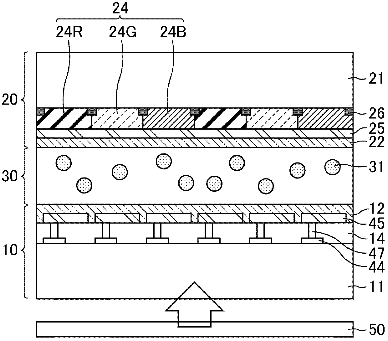
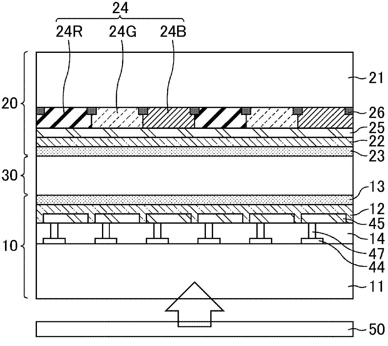
[0066] figure 1 and figure 2 is a schematic cross-sectional view of the liquid crystal display device according to the first embodiment. figure 1 Indicates that before the PSA polymerization process, figure 2 Indicates after the PSA polymerization step. Such as figure 1 and figure 2As shown, the liquid crystal display device of Embodiment 1 includes a liquid crystal display panel having an array substrate 10, an opposing substrate 20, and a liquid crystal sandwiched between a pair of substrates composed of the array substrate 10 and the opposing substrate 20. Layer 30. In addition, a backlight 50 is provided behind the liquid crystal display panel. The liquid crystal display device of Embodiment 1 performs display using light emitted from the backlight 50 . That is, the liquid crystal display device of Embodiment 1 is a transmissive liquid crystal display device.

[0067] The array substrate 10 includes: an insulating transparent substrate 11 made of glass or the...

Embodiment 1

[0096] The liquid crystal display panel of Embodiment 1 was actually manufactured, and the afterimage of the display was confirmed. The light source used in embodiment 1 is to have Figure 9 and Figure 10 The LEDs of the light emission spectrum shown do not have substantially any light having a wavelength below 400 nm. On the other hand, using the Figure 9 and Figure 10 In the CCFL with the emission spectrum shown, a very small peak (about 0.04 μW / cm 2 ).

[0097] First, a pair of substrates consisting of an array substrate and a counter substrate is prepared, a composition for forming a liquid crystal layer containing a liquid crystal material and a monomer for forming a PSA layer is dropped, and then bonded to the other substrate. The color filter is fabricated on the opposite substrate.

[0098] In Example 1, as a monomer for PSA layer formation, a compound represented by the following chemical formula (3) was used:

[0099]

[0100] The compound represented by...

Embodiment approach 2

[0108] The liquid crystal display device according to Embodiment 2 is in the form of a color filter array (COA: Color Filter On Array) formed on an array substrate instead of a color filter on an opposing substrate, and the light source is not limited to LEDs. Other than that, it is the same as Embodiment 1.

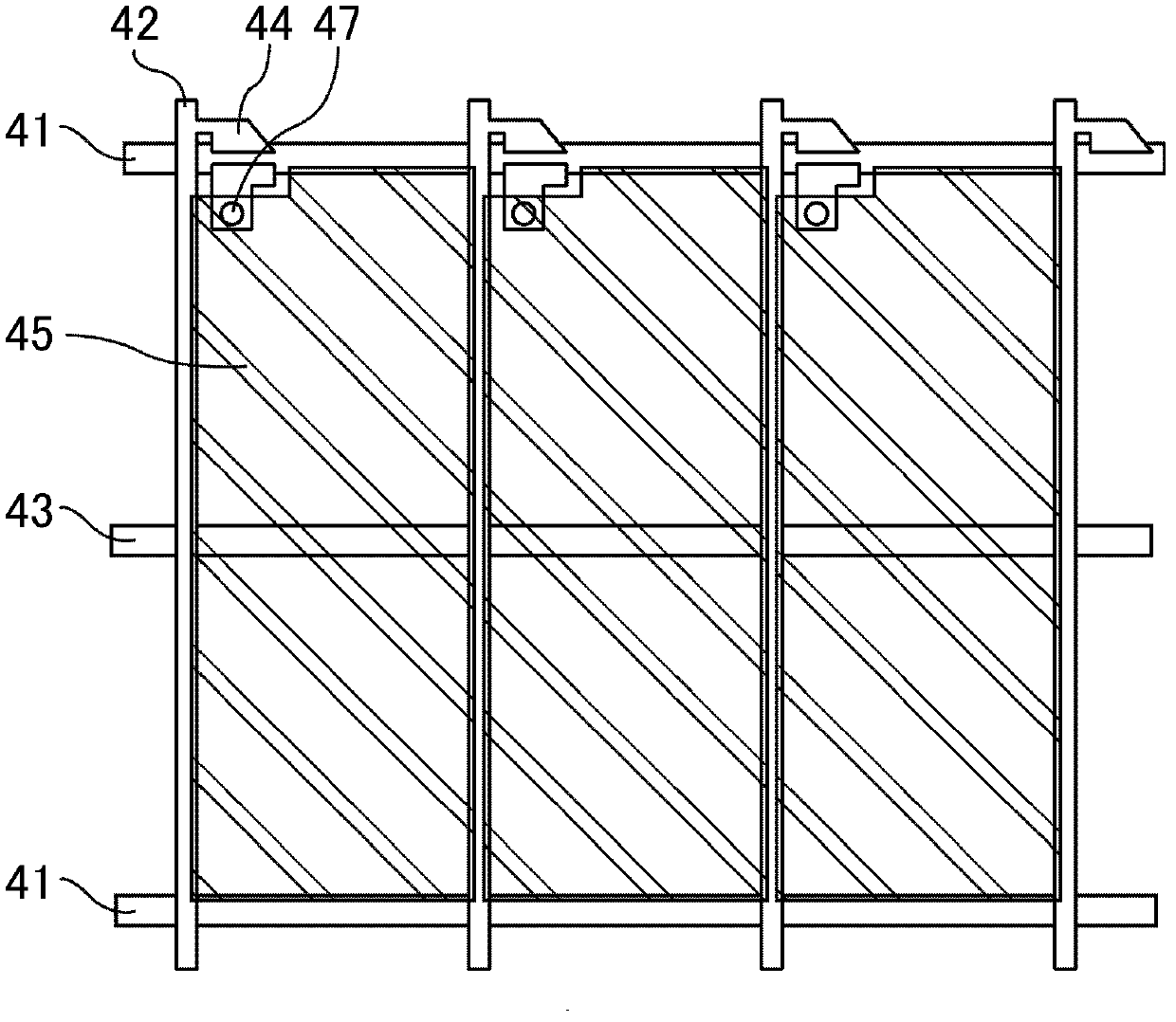
[0109] Figure 6 and Figure 7 is a schematic cross-sectional view of a liquid crystal display device according to Embodiment 2. FIG. Figure 6 Indicates that before the PSA polymerization process, Figure 7 Indicates after the PSA polymerization step. Such as Figure 6 and Figure 7 As shown, in the second embodiment, the color filter 24 and the black matrix 26 are formed on the array substrate 10 . More specifically, TFT 44 and bus lines (not shown) are arranged on an insulating transparent substrate 11 made of glass or the like, and black matrix 26 and color filters are arranged thereon via an insulating film (not shown). twenty four. In some cases, another in...


PUM

PropertyMeasurementUnit
wavelengthaaaaaaaaaa

Abstract

The present invention relates to a liquid crystal display device which has a polymer layer that is formed on an alignment film and controls the alignment of liquid crystal molecules adjacent thereto. The polymer layer is formed by polymerizing monomers that are added into a liquid crystal layer, and the monomers are compounds represented by general formula (I). P1-A1-(Z1-A2)n-P2 (I) (In the formula, P1 and P2 may be the same as or different from each other and each represents an acrylate group or a methacrylate group; in cases where there are a plurality of Z1 moieties, the Z1 moieties may be the same as or different from each other and each represents COO, OCO or O, or alternatively represents that A1 and A2 or A2 and A2 are directly bonded with each other; a hydrogen atom may be substituted by a halogen atom, a methyl group, an ethyl group or a propyl group; and A1 and A2 may be the same as or different from each other and each represents a specific phenanthrene group.) The light source of a backlight is composed of at least one light emitting diode, and each light emitting diode substantially emits only such light that has a wavelength of 400 nm or more.

Description

technical field [0001] The present invention relates to a liquid crystal display device. More specifically, it relates to a liquid crystal display device in which a polymer layer is formed on an alignment film in order to increase the alignment regulating force of liquid crystals. Background technique [0002] Liquid crystal display devices are widely used as display devices for televisions, computers, PDAs, and the like due to their thinness, lightness, and low power consumption. In particular, in recent years, liquid crystal display devices such as liquid crystal display devices for televisions have rapidly increased in size. When increasing the size, a multi-domain vertical alignment mode (MVA: Multi-domain Vertical Alignment) that can be manufactured with a high yield even if the area is large and has a wide viewing angle is preferably used. In the multi-liquid crystal domain vertical alignment mode, liquid crystal molecules are vertically aligned with respect to the s...

Claims


Application Information

Patent Timeline
Patent Type & Authority Applications(China)
IPC IPC(8): G02F1/1337C08F20/30G02F1/13357
CPCG02F1/133603C08F20/30G02F1/133617G02F1/133703
Inventor 仲西洋平水崎真伸野间健史山田祐一郎
Owner MERCK PATENT GMBH
Why Eureka
Try Eureka