Bionic coupling cast iron guide rail and manufacturing method thereof and regeneration method of waste machine tool guide rail

A guide rail, cast iron technology, applied in the direction of manufacturing tools, metal processing machinery parts, laser welding equipment, etc., can solve the problems of affecting the machining accuracy of machine tools, unable to guarantee machining accuracy, and scrapping of machine tools, and achieve excellent fatigue resistance and wear resistance, eutectic Small cluster size and improved tissue performance

Inactive Publication Date: 2013-05-22
JILIN UNIV
View PDF5 Cites 17 Cited by
  • Summary
  • Abstract
  • Description
  • Claims
  • Application Information

AI Technical Summary

Problems solved by technology

The failure of machine tool guide rails is mostly due to fatigue wear failure. During the tens of thousands of reciprocating motions of the guide rail, under the pressure of the workpiece load, a certain arc will be generated and no longer maintain the level, so that the machining accuracy cannot be guaranteed; at the same time, during the use of the machine tool , Pitting corrosion will inevitably appear on the surface of the guide rail, which will also affect the machining accuracy of the machine tool and cause the machine tool to be scrapped

Method used


Image

  • Bionic coupling cast iron guide rail and manufacturing method thereof and regeneration method of waste machine tool guide rail
  • Bionic coupling cast iron guide rail and manufacturing method thereof and regeneration method of waste machine tool guide rail
  • Bionic coupling cast iron guide rail and manufacturing method thereof and regeneration method of waste machine tool guide rail

Examples


Embodiment Construction

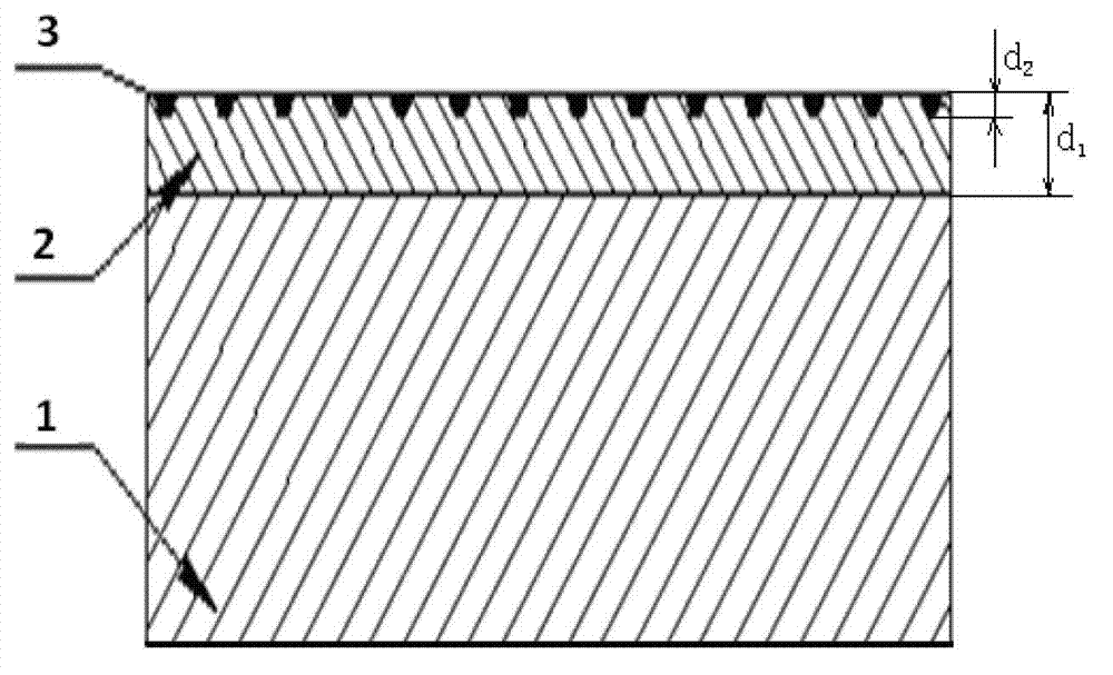
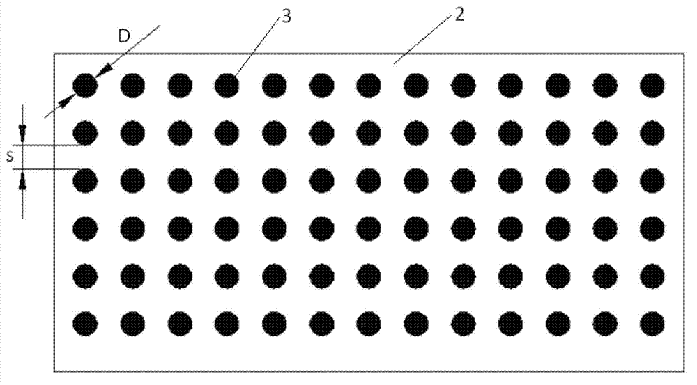
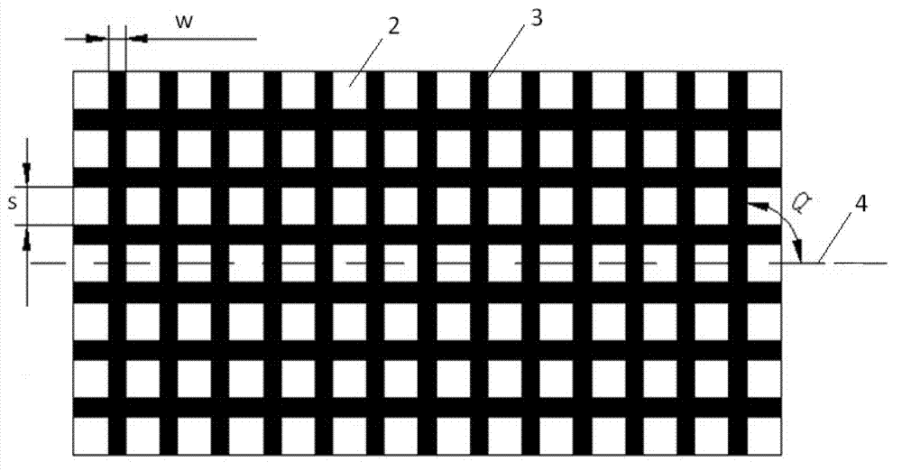
[0032] Such as figure 1 As shown, the biomimetic coupling cast iron guide rail of the present invention is composed of a guide rail main body 1 and its surface structure refinement layer 2; nano-scale martensite units 3 are distributed on the surface structure refinement layer 2. The average size of eutectic clusters in the surface structure refinement layer 2 is 0.01-0.3 mm. Depth d of surface texture refinement layer 2 1 The range is 0.8-2mm. The unit body 3 can be cylindrical (such as figure 2 shown), the diameter D is 0.5~4mm, the spacing s is 0.5~4mm, and the depth d 2 0.1-0.8mm, and the cylindrical units are uniformly or randomly distributed on the surface texture refinement layer 2 . The unit body 3 can also be in the form of a grid formed by stripes intersecting (such as image 3 shown), the stripe width w of the grid-like unit body is 0.5-4mm, the spacing s is 0.5-4mm, the inclination angle α (that is, the angle between the stripe unit body and the guide rail ax...


PUM

PropertyMeasurementUnit
sizeaaaaaaaaaa
depthaaaaaaaaaa
diameteraaaaaaaaaa

Abstract

The invention relates to a bionic cast iron guide rail and a manufacturing method of the bionic cast iron guide rail and a regeneration method of a waste machine tool guide rail. The cast iron guide rail is composed of a guide rail main body and a surface structure refining layer of the guide rail main body. Nanoscale martensite units are distributed on the surface structure refining layer. The manufacturing method of the cast iron guide rail and the regeneration method of the waste machine tool guide rail mainly comprise the following steps of obtaining the surface structure refining layer by using high-frequency electric pulses to process the guide rail, and manufacturing the nanoscale martensite units on the surface structure refining layer by the adoption of laser fusing method. The units and a guide rail parent together form a bionic coupling area which is soft and hard and resembles a living body structure, the units function as firm pile screws or reinforcing ribs which are additionally arranged on the surface layer of the guide rail, and parent materials surround the units and enable the unit to be connected into a whole so as to enable local peak values of the surface of the guide rail to be dispersed and stress of the guide rail to be even. The bionic cast iron guide rail has superior mechanic property and fatigue and abrasion resistant performance.

Description

technical field [0001] The invention belongs to the technical field of cast iron guide rails, and relates to a bionic coupling cast iron guide rail and a manufacturing method thereof, as well as a regeneration method for waste machine tool guide rails. Background technique [0002] In the machinery industry, machine tools are usually referred to as machine tools, which are the basic processing equipment in the machinery manufacturing industry. Its variety, performance, quality and technical level directly affect the performance, quality, production technology level and economics of other mechanical and electrical products. benefit. my country is the largest machine tool consumer market in the world. Currently, there are about 8 million machine tools. According to the internationally accepted reduction rate of 3%, about 250,000 old machine tools are eliminated every year, and the total metal weight exceeds 1.5 million tons. For an old machine tool, there are generally more t...

Claims


Application Information

Patent Timeline
Patent Type & Authority Applications(China)
IPC IPC(8): B23Q1/01B23P6/00B23K26/00B23K26/354
Inventor 周倜周宏庞作波任露泉张志辉王传伟丛大龙孟超
Owner JILIN UNIV
Why Eureka
Try Eureka