Simulation experiment method and system for thermal treatment of oily sludge

A technology for simulating experiments and sludge, applied in the field of oily sludge heat treatment

Inactive Publication Date: 2013-05-22
PETROCHINA CO LTD
View PDF5 Cites 19 Cited by
  • Summary
  • Abstract
  • Description
  • Claims
  • Application Information

AI Technical Summary

Problems solved by technology

[0005] The above related research devices are mainly heated by conduction and radiation. Due to the limitation of furnace type and material, this heating method will cause serious coking.

Method used


Image

  • Simulation experiment method and system for thermal treatment of oily sludge
  • Simulation experiment method and system for thermal treatment of oily sludge
  • Simulation experiment method and system for thermal treatment of oily sludge

Examples


Embodiment 1

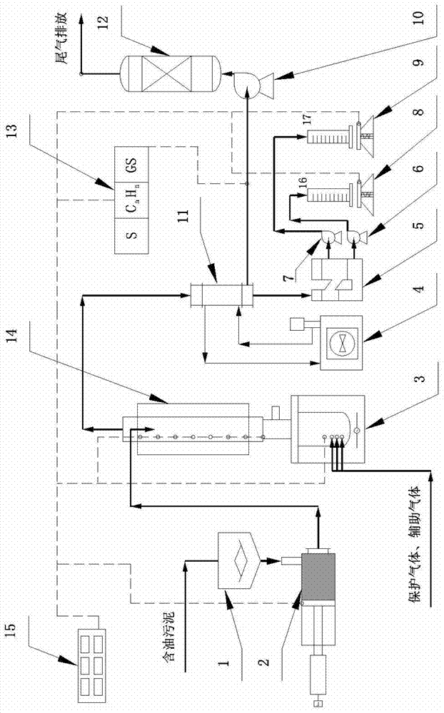
[0050] This embodiment provides a simulation experiment system for heat treatment of oily sludge, its structure is as follows figure 1 As shown, the system includes a homogenizer 1, a sludge booster conveyor 2, a mass transfer heat transfer reactor 14, a heating furnace 3, a circulating cooling water device 4, an automatic oil-water separation device 5, and a first liquid level control pump 6 , the second liquid level control pump 7, pyrolysis water metering electronic scale 8, water collection container 16, pyrolysis oil metering electronic scale 9, oil collection container 17, induced draft fan 10, distillate condenser 11, thermal oxidation tower 12 , Online gas component detector 13, detection and control device 15, wherein:

[0051] The homogenizer 1 is provided with a material inlet and an outlet, and its outlet is connected to the inlet of the sludge pressurized conveyor 2;

[0052] The sludge booster conveyor 2 is connected to the top feed port of the mass transfer hea...

Embodiment 2

[0061] This embodiment provides a simulation experiment method for heat treatment of oily sludge, which is a method for analyzing oily sludge samples using the simulation experiment system for heat treatment of oily sludge provided in Example 1, including the following steps:

[0062] 40kg of oily sludge was placed in the homogenizer 1 and stirred for 30 minutes. Three samples were taken for detection: the water content was 75.1%, 75.2%, and 74.8%; the oil content was 13.6%, 13.4%, and 13.5%; the relative error is less than 4%, it is considered that the sludge is evenly mixed, and the experiment is continued;

[0063] Turn on the power supply of auxiliary systems such as the induced draft fan 10, the circulating cooling water device 4, the pyrolysis water metering electronic scale 8, the pyrolysis oil metering electronic scale 9 and the thermal oxidation tower 12, open the operating system, and check whether the remote signals are normal;

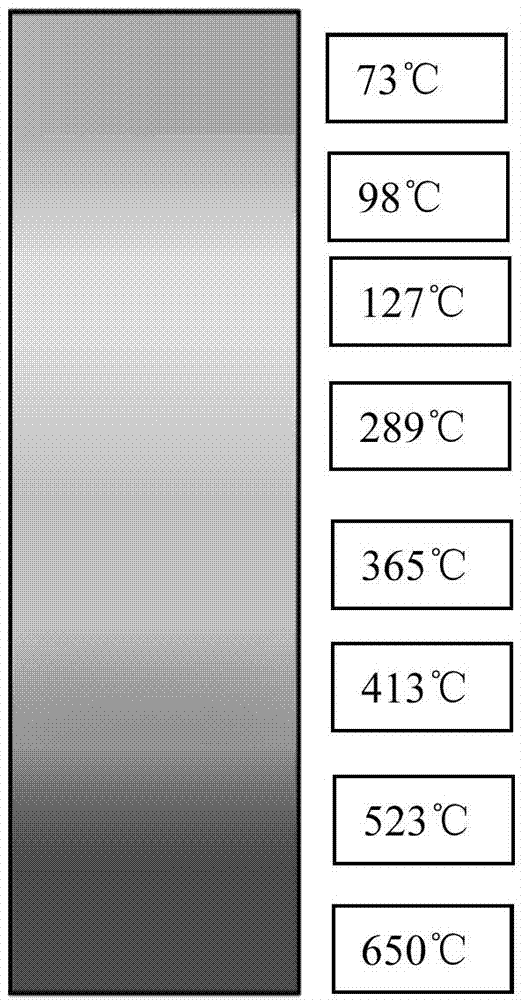
[0064] Open the heating furnace 3, h...


PUM

PropertyMeasurementUnit
heightaaaaaaaaaa
particle diameteraaaaaaaaaa

Abstract

The invention relates to a simulation experiment method and system for thermal treatment of oily sludge. The method comprises the following steps of: stirring oily sludge simulation samples, removing particles of which the particle sizes are more than 3mm, detecting moisture content and oil length of the samples, and carrying out thermogravimetric analysis on the samples; conveying the samples to the top part of a reactor, and measuring the number of input samples; feeding the samples into the reactor from the top part of the reactor, carrying out heating and gas contact to obtain a gas mixture and a solid component, detecting the temperature distribution inside the reactor, removing the solid component from the bottom part of the reactor, heating the solid component to obtain pyrolysis gas and waste residues, feeding the pyrolysis gas into the reactor from the bottom part to contact the samples, and sampling and detecting the discharged waste residues; and measuring the real-time output and the total quantity of the gas mixture, condensing and separating the gas mixture to obtain moisture, oil components and non-condensable gas, measuring the real-time output and the total quantity of the moisture, the oil components and the non-condensable gas, and detecting and analyzing the components of the non-condensable gas. The invention further provides the simulation experiment system for thermal treatment of oily sludge.

Description

technical field [0001] The invention relates to a simulation experiment method and a simulation experiment system for heat treatment of oily sludge, belonging to the technical field of oily sludge heat treatment. Background technique [0002] Oily sludge is a solid waste listed in the "National Hazardous Waste List" and has always been an environmental protection problem in the petroleum and petrochemical industry. Oily sludge is usually in a solid or semi-fluid state, and is a heterogeneous multiphase dispersion system, mainly composed of crude oil, water, clay minerals, biological organic matter and chemical additives. The oil content is generally about 10%, and the highest can reach 20%. %-30%, has the value of energy material recovery and mineral regeneration. [0003] Relevant domestic research institutes and colleges and universities began to study the pyrolysis treatment technology of oily sludge around 2000, and most of them used small static experimental devices fo...

Claims


Application Information

Patent Timeline
Patent Type & Authority Applications(China)
IPC IPC(8): G01N33/24
Inventor 王万福刘鹏邓皓刘光全雍兴跃屈一新
Owner PETROCHINA CO LTD
Why Eureka
Try Eureka