Z-direction magnetic field sensor with magnetic orbit structure

A magnetic field sensor and magnetic track change technology, applied in the field of weak signal sensing, can solve the problems of difficulty in guaranteeing consistency, limited resolution, and high difficulty, and achieve the effects of simple and compact structure, guaranteed orthogonality, and low cost.

Active Publication Date: 2013-05-22
NAT UNIV OF DEFENSE TECH
View PDF15 Cites 25 Cited by
  • Summary
  • Abstract
  • Description
  • Claims
  • Application Information

AI Technical Summary

Problems solved by technology

2. The sensor for measuring the Z-direction magnetic field in the vertical plane is placed on the slope, and the three-axis measurement is realized together with the in-plane sensors for measuring the X and Y-direction magnetic fields (patent numbers: US7564237, US7126330), which realizes integrated production, but the slope The MR magnetic sensor on the surface is relatively difficult to manufacture, and the consistency with the in-plane magnetic sensor is difficult to guarantee
4. Another person uses CMOS technology to realize a three-axis magnetic field sensor based on the Hall effect on a silicon chip, which ensures the orthogonality between the three axes, no hysteresis effect, and does not require special magnetic materials, and can be measured simultaneously Three components, but the resolution is low, about 21μT
5. Using micromachining technology to use thermal stress on the GaAs substrate to make the manufactured Hall sensor roughly perpendicular to the substrate plane to form a three-axis Hall sensor, which realizes the miniaturization and integrated design and manufacture of the three-axis magnetic sensor, and the process flow is relatively Simple, but it is difficult to accurately control the angle between the Z-direction sensor and the plane, and it is difficult to guarantee the orthogonality between all three axes, and the minimum detectable value is around 2μT
6. Someone used the principle of changing the output of the piezoresistive sensitive element by using the interaction force between the permanent magnet film and the external magnetic field, and used MEMS processing technology to realize the integrated design of the three-axis magnetic sensor on the silicon chip, ensuring the miniaturization and integration of the sensor , but the resolution that can be achieved is limited. At present, the measurement resolution of its Z-direction magnetic field is 250nT
7. Since the current-carrying conductor placed in the magnetic field will be subjected to the force of the Lorentz force, this force will be displaced through structural design, causing a change in capacitance, and the magnetic field value can be obtained by measuring the capacitance. The Lorentz force using MEMS technology Zili three-axis magnetic sensor has no hysteresis effect and does not require special magnetic materials. It can guarantee orthogonality, miniaturization, and low power consumption. However, the resolution achieved by this principle of magnetic sensor is not high. At present, The measurement resolution of the Z component is about 70nT, which is lower than the resolution of the in-plane magnetic field measurement
[0007] In general, the integrated three-axis magnetic sensor has better orthogonality than the assembled type, and the miniaturization of the sensor can be realized by using micromachining technology, but based on Hall elements, AMR elements, and Lorentz force resonance magnetic sensitive elements, The overall resolution is low; using GMR as a sensitive element can generally achieve higher sensitivity and resolution, but GMR is sensitive to the magnetic field in the plane, and the magnetic field in the vertical plane has little effect on it
Placing a soft magnetic block near the GMR sensitive element can transfer the Z-direction magnetic force lines to the plane for measurement to a certain extent, but the above various placement methods are difficult to implement in practice, and it is difficult to ensure the structural symmetry and Consistency of performance; making the GMR sensitive element on the slope of the sensor substrate can directly measure the Z-direction magnetic field, but its implementation method is also relatively complicated, and the distance between the magnetic sensors located on the slope and between the magnetic sensors in the plane Consistency is also difficult to guarantee
Therefore, the difficulty of technology development in the prior art lies in how to use GMR sensitive elements to measure the Z-direction magnetic field. This difficulty makes it difficult to realize the design and manufacture of a three-axis integrated magnetic sensor based on GMR sensitive elements.

Method used


Image

  • Z-direction magnetic field sensor with magnetic orbit structure
  • Z-direction magnetic field sensor with magnetic orbit structure
  • Z-direction magnetic field sensor with magnetic orbit structure

Examples


Embodiment Construction

[0024] The present invention will be further described in detail below in conjunction with the accompanying drawings and specific embodiments.

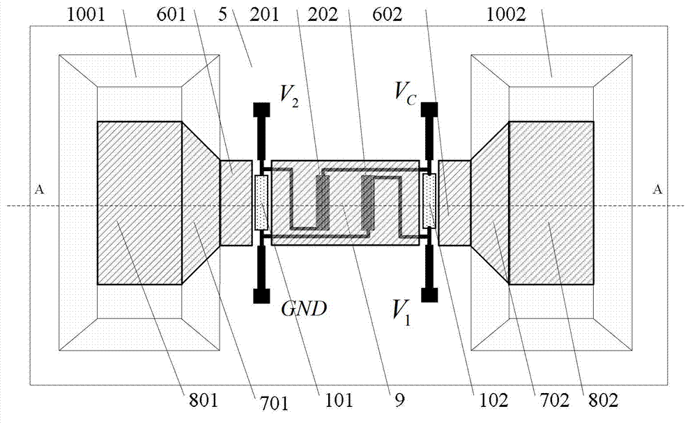
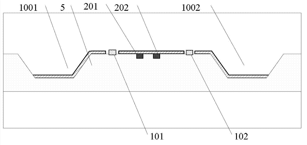
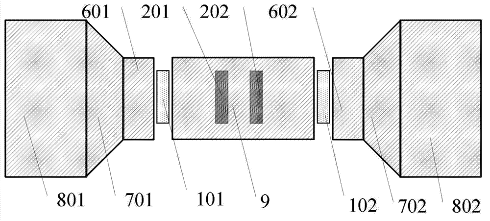
[0025] Such as figure 1 and figure 2 As shown, the Z-direction magnetic field sensor adopting the magnetic track structure of the present invention includes a substrate 5, two pairs of input and output electrodes, two pairs of GMR sensitive elements and GMR reference elements, and symmetrically arranged magnetic flux concentrators. Two pairs of input and output electrodes are plated on the surface of the substrate 5, namely: each pair includes a set of Wheatstone bridge bias electrodes and Wheatstone bridge signal output electrodes, the first Wheatstone bridge bias electrode 301 and the first Wheatstone bridge bias electrode 301 and the first Wheatstone bridge bias electrode 301 The bridge signal output electrode 401 is a pair, and the second Wheatstone bridge bias electrode 302 and the second Wheatstone bridge signal output electro...


PUM


Abstract

A z-direction magnetic field sensor with a magnetic orbit structure comprises a basement, two pairs of input electrodes and output electrodes, two pairs of giant magneto resistive (GMR) sensitive elements and GMR reference elements and an accumulator of magnetic line of force arranged in a symmetrical mode. The two pairs of the input electrodes and the output electrodes are plated on the surface of the basement, and each pair of the GMR sensitive element and the GMR reference element and each pair of the input electrode and the output electrode form a Wheatstone bridge. A first pit and a second pit are arranged on the basement in a symmetrical mode, the Wheatstone bridge is arranged between the first pit and the second pit, edges of the inner planes of the first pit and the second pit and slopes of the first pit and the second pit and the pits are all provided with soft magnetic films in a plating mode to form an inner accumulator of the pit, the slope accumulator of the pit, and the edge accumulator of the pit in sequence, due to the fact that a central accumulator is arranged in the middle area between the first pit and the second pit, the accumulator of the magnetic line of force is formed. The z-direction magnetic field sensor with the magnetic orbit structure has the advantages of being simple and compact in structure, small in size, low in cost, convenient to manufacture, and high in resolution capability and the like.

Description

technical field [0001] The invention mainly relates to the technical field of weak signal sensing, in particular to a Z-direction magnetic field sensor adopting a magnetic track structure. Background technique [0002] Weak magnetic field measurement is widely used in geomagnetic navigation, target detection, geological exploration, biomedicine and other fields. The three-axis magnetic sensor can measure the three components of the magnetic field at the same time, and calculate the inclination and azimuth of the sensor. Low power consumption and miniaturization are the main development directions of three-axis magnetic sensors. [0003] At present, there are many types of three-axis magnetic sensors used for magnetic field measurement. According to the implementation method, they can be divided into assembled type and integrated type. According to their working principles, they can be divided into fluxgate sensors, Hall sensors, Lorentz force magnetic sensors, GMR (Giant M...

Claims


Application Information

Patent Timeline
Patent Type & Authority Applications(China)
IPC IPC(8): G01R33/09
Inventor 胡佳飞田武刚赵建强张琦潘孟春李季胡靖华
Owner NAT UNIV OF DEFENSE TECH
Why Eureka
Try Eureka