Hole processing method for which low-melting-point alloy sacrificial layer is adopted

A hole processing method and low melting point technology, applied in the field of electrolytic machining, can solve the problems of out-of-tolerance hole diameter, scrapped parts, affecting the consistency of hole diameter at the exit of a group of holes, etc., to improve versatility, avoid secondary corrosion, and improve processing stability. Effect

Active Publication Date: 2013-06-05
NANJING UNIV OF AERONAUTICS & ASTRONAUTICS
View PDF6 Cites 7 Cited by
  • Summary
  • Abstract
  • Description
  • Claims
  • Application Information

AI Technical Summary

Problems solved by technology

This will greatly affect the consistency of the exit aperture of the group of holes, causing the aperture to be out of tolerance and the parts to be scrapped

Method used


Image

  • Hole processing method for which low-melting-point alloy sacrificial layer is adopted
  • Hole processing method for which low-melting-point alloy sacrificial layer is adopted
  • Hole processing method for which low-melting-point alloy sacrificial layer is adopted

Examples


Embodiment Construction

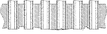
[0032] figure 1 In the process, the thickness of the part is not uniform, and the group holes appear successively through;

[0033] figure 2 In the process, the group of holes appear to penetrate successively, and the holes that penetrate first will undergo secondary corrosion, forming trumpet-shaped small holes;

[0034] Figure 4 In the process, the low-melting point alloy is coated on the exit position of the predetermined machining hole of the part;

[0035] Figure 5 In, after coating the low melting point alloy, the current is redistributed and the secondary corrosion is avoided.

[0036] to combine Figure 4 , 5 , 6, illustrate the implementation process of the present invention:

[0037] (1). Use the method of spraying to evenly coat the molten low-melting point alloy at the exit position of the predetermined machining hole of the workpiece, and cool it in the air;

[0038] (2). Electrolytic processing of tube electrodes;

[0039] (3). After processing, heat ...


PUM

PropertyMeasurementUnit
pore sizeaaaaaaaaaa

Abstract

The invention relates to a hole processing method for which a low-melting-point alloy sacrificial layer is adopted and belongs to the technical field of electrochemical machining. The hole processing method comprises a first step of coating molten low-melting-point alloy at the position of an outlet of a predetermined processing hole of a workpiece in a spray method, cooling the low-melting-point alloy in the air, and forming the low-melting-point alloy layer; a second step of performing tube electrode electrochemical machining; a third step of removing the low-melting-point alloy layer after processing is finished; and a fourth step of cleaning a part. The method is of great significance for improving process stability and processing accuracy of the tube electrode electrochemical machining.

Description

Technical field [0001] The hole processing method using a low melting point alloy sacrificial layer of the invention belongs to the technical field of electrolytic processing. Background technique [0002] With the continuous increase of the temperature before the turbine of the aero-engine, the film cooling technology is widely used in the hot-end parts of the engine. The film cooling holes of the turbine blade and the film cooling holes of the combustion chamber flame tube are indispensable key structures in the aero-engine, and their manufacturing quality directly affects the performance of the aero-engine. The diameter of the film cooling hole is generally between 0.25-1.8mm. There are many holes and the angle changes greatly. Difficult-to-machine materials such as nickel-based superalloys, nickel-based intermetallic compounds, and titanium alloys are often used, and the processing surface quality is high. The existence of recasting layer and microcracks is allowed, so ...

Claims


Application Information

Patent Timeline
Patent Type & Authority Applications(China)
IPC IPC(8): B23P17/00
Inventor 曲宁松房晓龙张玉冬朱荻
Owner NANJING UNIV OF AERONAUTICS & ASTRONAUTICS
Why Eureka
Try Eureka