Heat pipe grinding wheel for dry cutting for difficult-to-machined materials and method for manufacturing heat pipe grinding wheel

A heat pipe grinding wheel, a technology that is difficult to process, applied in the direction of grinding devices, bonded grinding wheels, metal processing equipment, etc., can solve the problems of heat pipe grinding wheels staying in the conceptual stage, temperature rise in the grinding arc area, residual stress microcracks, etc. Achieve the effects of quick start-up, improved heat transfer performance, and easy production

Active Publication Date: 2013-06-05
NANJING UNIV OF AERONAUTICS & ASTRONAUTICS
View PDF6 Cites 24 Cited by
  • Summary
  • Abstract
  • Description
  • Claims
  • Application Information

AI Technical Summary

Problems solved by technology

[0002] When grinding difficult-to-machine materials, most of the heat generated is accumulated in the grinding arc area. Due to the poor thermal conductivity of the difficult-to-machine materials themselves, the temperature in the grinding arc area rises sharply. If the grinding arc area cannot be controlled in time and effectively temperature, it may cause thermal damage such as oxidation, burns, residual stress and microcracks on the surface of parts
The traditional cooling method is to pour a large amount of coolant into the grinding arc area. The use of a large amount of coolant not only i...

Method used


Image

  • Heat pipe grinding wheel for dry cutting for difficult-to-machined materials and method for manufacturing heat pipe grinding wheel
  • Heat pipe grinding wheel for dry cutting for difficult-to-machined materials and method for manufacturing heat pipe grinding wheel
  • Heat pipe grinding wheel for dry cutting for difficult-to-machined materials and method for manufacturing heat pipe grinding wheel

Examples


Embodiment Construction

[0048] In order to make the content of the present invention easier to understand, the content of the present invention will be described in detail below in conjunction with the accompanying drawings.

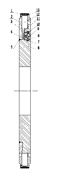
[0049] The heat pipe grinding wheel includes abrasive grains 1, end cover 2, condensation groove 3, end face sealing ring 4, weld seam 5, base 6, radial sealing ring 7, radial sealing ring 8, inner plug 9, outer plug 10, Air pump hole 11, lumen 12, liquid film 13.

[0050] The manufacturing process of the heat pipe grinding wheel for dry grinding of practical difficult-to-machine materials is as follows:

[0051] Step 1), making the end cover 2, the base 6, the inner plug 9, and the outer plug 10 of the heat pipe grinding wheel;

[0052]Step 2), match the end cap 2 with the base 6, and fix it with a clamp; pass argon gas through the hole of the plug to fill the cavity of the heat pipe with argon gas to prevent high-temperature oxidation of the heat pipe wall during welding, an...


PUM

PropertyMeasurementUnit
Wall thicknessaaaaaaaaaa

Abstract

The invention discloses a heat pipe grinding wheel for dry cutting for difficult-to-machined materials and a method for manufacturing the heat pipe grinding wheel. The heat pipe grinding wheel comprises a matrix and abrasive particles arranged on the matrix, and is characterized in that the matrix comprises a base and an end cover, the abrasive particles are arranged on the end cover, solid lubricants are coated on the abrasive particles, a heat pipe cavity is further formed between the end cover and the base, an air exhaust hole is further arranged on the base, the inside of the air exhaust hole is communicated with the heat pipe cavity, a plug hole is arranged on the outside of the air exhaust hole, an inner plug and an outer plug which are coaxially arranged are disposed in the plug hole, working media are arranged in the heat pipe cavity, and condensation grooves are arranged on two outer surfaces, which are positioned in a condensation section of the heat pipe cavity, of the end cover at intervals. The heat pipe grinding wheel and the method have the advantages that the structure is simple, the cost is low, heat of a grinding arc area can be effectively dissipated when the difficult-to-machined materials are machined, and the bottleneck problem that coolant is difficult to be filled into an existing grinding arc area for effective heat exchange can be solved.

Description

Technical field: [0001] The invention relates to a structural improvement of a heat pipe grinding wheel for dry grinding of difficult-to-machine materials, and belongs to the field of high-efficiency grinding and grinding tools for difficult-to-machine materials. Background technique: [0002] When grinding difficult-to-machine materials, most of the heat generated is accumulated in the grinding arc area. Due to the poor thermal conductivity of the difficult-to-machine materials themselves, the temperature in the grinding arc area rises sharply. If the grinding arc area cannot be controlled in time and effectively If the temperature is too high, it may cause thermal damage such as oxidation, burns, residual stress and microcracks on the surface of the part. The traditional cooling method is to pour a large amount of coolant into the grinding arc area. The use of a large amount of coolant not only increases the processing cost, but also pollutes the environment and even endan...

Claims


Application Information

Patent Timeline
IPC IPC(8): B24D5/10B24D18/00
Inventor 傅玉灿陈佳佳赫青山陈琛张玮
Owner NANJING UNIV OF AERONAUTICS & ASTRONAUTICS
Why Eureka
Try Eureka