System and control method of engine position management

A management system and engine technology, applied in the direction of engine control, machine/engine, electrical control, etc., can solve problems such as time-consuming, misjudgment of signal jump edge, slow vehicle start, etc., to improve driving comfort and increase fault tolerance , the effect of increasing safety

Active Publication Date: 2013-06-05
LIANCHUANG AUTOMOBILE ELECTRONICS
View PDF3 Cites 17 Cited by
  • Summary
  • Abstract
  • Description
  • Claims
  • Application Information

AI Technical Summary

Problems solved by technology

The length of the process from engine start to normal operation often affects the sensory enjoyment of the user. If the ignition time of the starter key is too short, the ECU has not had time to complete the detection of the synchronization position, and the engine cannot work normally, which will cause complaints from customers.
The traditional synchronous detection method is to set and capture the jump edge of the camshaft position signal in the camshaft position signal acquisition channel, but in the actual engine operating conditions, the ECU will cause the camshaft position signal to jump due to signal clutter and noise. Misjudgment of variable edge
Although the method of detection and verification can be used to verify the synchronization in the next engine cycle, it takes extra time and makes the user feel that the vehicle starts slowly, which cannot bring a good user experience

Method used


Image

  • System and control method of engine position management
  • System and control method of engine position management
  • System and control method of engine position management

Examples


Embodiment Construction

[0025] The structural block diagram of the engine position management system is as follows Image 6 As shown, it includes: crankshaft signal processing module, camshaft signal processing module and synchronous logic processing module.

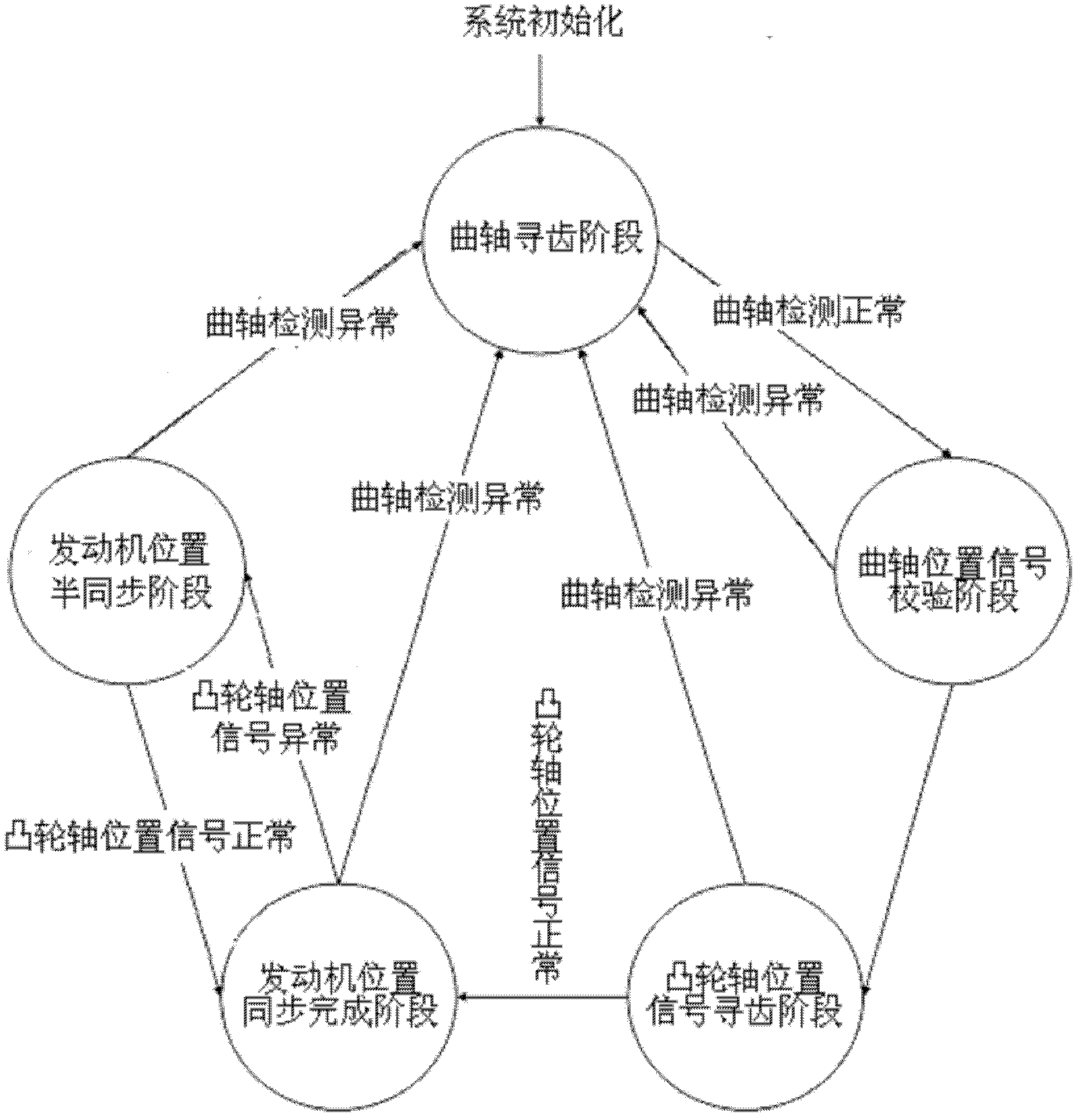
[0026] Such as figure 1 As shown, in the engine position management system, the engine position synchronization process includes five stages, namely: the crankshaft gear search stage, the crankshaft position signal verification stage, the camshaft position signal tooth search (search) stage, and the engine position synchronization completion stage Semi-synchronous phase with engine position.

[0027] The crankshaft gear-seeking stage refers to debounce and filter processing before detection of the starting waveform of the crankshaft position signal during system initialization during engine control. When the engine is driven by the starter motor guided by the ignition key, in order to ensure the correctness and stability of the tooth signal, ...


PUM


Abstract

The invention discloses a system of engine position management. According to the system of the engine position management, an enhancement mode time processing unit (ETPU) is adopted to achieve rapid and synchronic fault-tolerance. According to a crank signal processing module, a jumping edge of a crank position signal detected by an input crank position sensor is collected for several times. According to a cram shaft signal processing module, electrical level and a jumping edge of a cram shaft position signal detected by an input cram shaft position sensor are collected for several times in a mixing mode. According to a synchronous logical processing module, a crank state quantity signal output by the crank signal processing module and a cram shaft state quantity signal output by the cram shaft signal processing module are processed and analyzed and a synchronous state quantity signal is output so that an engine state can be changed in real time and synchronism of a crank and a cram shaft is finally achieved. The invention further discloses a control method for the engine position management. The system and the method are capable of achieving the process of the synchronism of an engine rapidly and steadily.

Description

technical field [0001] The invention relates to a control system of engine position detection synchronization logic, in particular to a fast synchronization fault-tolerant engine position management system using an eTPU (enhanced time processing unit) unit. The invention also relates to a control method for engine position management with an eTPU unit. Background technique [0002] In order to improve the economy, stability and emission of contemporary diesel engines, it is imperative to adopt advanced control units. The key point of engine control is to find the mechanical position of the engine to determine the top dead center position of the piston for accurate fuel injection. At present, the industry mainly collects the crankshaft position signal and the camshaft position signal at the same time, and combines the two signals to calculate and judge as the main means of engine position measurement. [0003] The underlying drive of the engine is mainly divided into two pa...

Claims


Application Information

Patent Timeline
Patent Type & Authority Applications(China)
IPC IPC(8): F02D45/00
Inventor 俞明盛旭威刘翔童毅韩本忠
Owner LIANCHUANG AUTOMOBILE ELECTRONICS
Why Eureka
Try Eureka