Method and system for measuring stray light

A measurement system and stray light technology, applied in measurement devices, photometry, optical radiation measurement, etc., can solve the problems of changes in the steepness of the sidewall of the pattern, large environmental impact, and reduced depth of focus, avoiding high costs and costs. Low, avoid the effect of environmental impact

Inactive Publication Date: 2013-06-05
INST OF OPTICS & ELECTRONICS - CHINESE ACAD OF SCI
View PDF4 Cites 10 Cited by
  • Summary
  • Abstract
  • Description
  • Claims
  • Application Information

AI Technical Summary

Problems solved by technology

[0010] (6) Stray light can also cause changes in the steepness of the side walls of the graphics
[0011] (7) Stray light will cause the depth of focus to decrease
Because this stray light detectio

Method used


Image

  • Method and system for measuring stray light
  • Method and system for measuring stray light
  • Method and system for measuring stray light

Examples


Embodiment Construction

[0062] In order to better illustrate the purpose and advantages of the present invention, the present invention will be further described below in conjunction with the accompanying drawings.

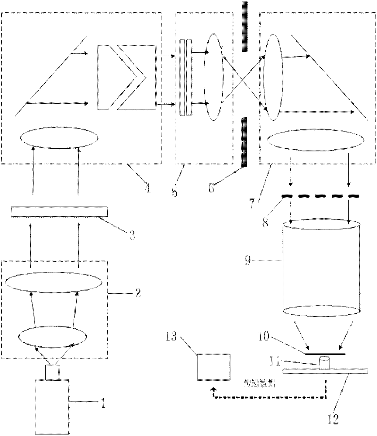
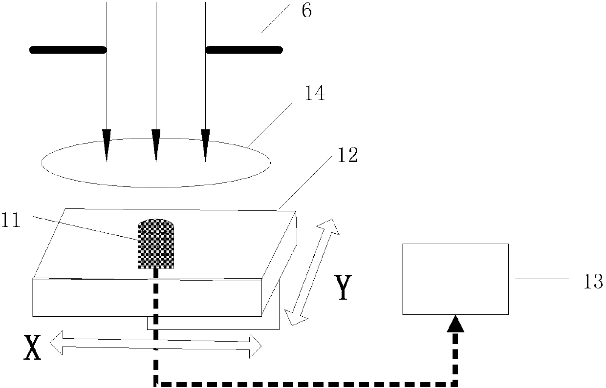
[0063] like figure 1 A schematic diagram showing the system for measuring stray light including various functional components of the photolithography part and the stray light detection part, figure 2 A schematic diagram of the measurement system for stray light and the whole field deviation of stray light is shown, figure 1 The functional components of the lithography department include a light source 1, a beam expander unit 2, a beam mode conversion unit 3, a coherence factor adjustment unit 4, a uniform light unit 5, an imaging unit 7, a mask surface 8, a lithography projection objective lens 9, silicon One-sided 10. The stray light detection part comprises a variable slit 6, a point energy detector 11, a displacement platform 12 and a computer 13, the point energy detector 11 is lo...


PUM


Abstract

The invention provides a method for measuring stray light. The method comprises the following steps of: S1, initializing a displacement platform; S2, setting measuring parameters of a measuring system; S3, driving the displacement platform by a driving motor to scan an illumination light field region, performing light energy detection on a test point on a mask surface or a silicon slice surface by using a point energy detector, fixing the point energy detector at the position of a test point, adjusting the size of an opening of a changeable slit to obtain light energy values of the same test point at different openings of the variable slit; S4, for different test points in the illumination light field region, repeating the step S3 to measure different light energy values at different openings of the variable slit; and S5, storing light energy value data into a computer through a serial port communication, and performing data processing on the light energy value data by the computer to obtain the stray light of each test point on the mask surface or the silicon slice surface. The invention also provides a system for measuring the stray light.

Description

technical field [0001] The invention belongs to the technical field of modern optical testing, and relates to the accurate measurement of the stray light of a lithography illumination system and a lithography projection objective lens system and the whole-field deviation of the stray light. Background technique [0002] Stray light, also known as stray light or stray light radiation, refers to the non-imaging light radiation energy diffused on the surface of the detector in addition to the imaging light in the optical system, as well as the imaging light radiation energy reaching the detector through an abnormal optical path. . The whole field deviation of stray light refers to the deviation of stray light at different test points in the field of view. In the lithography system, it refers to the non-imaging light diffused on the mask and silicon wafer, which has a negative impact on the imaging quality and CD (Critical dimension) uniformity of the lithography pattern. [0...

Claims


Application Information

Patent Timeline
IPC IPC(8): G03F7/20G01J1/00G01J1/04
Inventor 范真节邢廷文林妩媚黄智强
Owner INST OF OPTICS & ELECTRONICS - CHINESE ACAD OF SCI
Why Eureka
Try Eureka