Supercharge Your Innovation With Domain-Expert AI Agents!

Packaging structure of intelligent power module

A technology of intelligent power modules and packaging structures, applied in the direction of support structure installation, etc., can solve the problems of long process time, high bending process requirements, and poor welding performance, so as to improve the firmness and reliability, and solve the problem of excessive contact resistance. The effect of large, good size and flatness

Active Publication Date: 2015-12-23
DELTA ELECTRONICS (SHANGHAI) CO LTD
View PDF4 Cites 0 Cited by
  • Summary
  • Abstract
  • Description
  • Claims
  • Application Information

AI Technical Summary

Problems solved by technology

[0003] At present, most of the terminals on the power module are sintered on the metal layer of the cermet-clad substrate by solder at high temperature. The terminals include electrode terminals and signal terminals. The welding stress is generated at the place, and the working environment of the intelligent power module is cycled at -40°C to 125°C, so after a period of work, the metal layer of the metal-ceramic substrate and the terminal connection will eventually fall off, resulting in welding fatigue phenomenon, thus affecting the life of the overall power device
Secondly, the terminals are welded on the metal layer of the cermet-clad substrate with solder, which not only has high requirements on the surface of the metal layer of the cermet-clad substrate and the surface of the terminal, especially the metal layer of the cermet-clad substrate, that is, the copper foil and the copper material of each terminal. There will also be a difference in thermal expansion between them, and the welding performance is not high, which will affect the electrical conductivity
At the same time, the welding process not only requires solder, flux and protective gas during welding, not only the high-temperature sintering welding process takes a long time, but also the high temperature generated can easily lead to weakening of the metal properties of other parts of the material, and the solder flow and solder resistance during the welding process Factors such as ink will cause the risk of contamination on the welding surface. The existing terminal welding has the problems of difficult control of the welding surface, complicated process operation, and low welding efficiency.
Furthermore, the electrode terminal needs to be bent, but the bending strength and angle of the electrode terminal are not easy to control, which makes the bending process more demanding. On the one hand, the electrode terminal will also have cracks at the bend. Causes problems with increased local resistance
On the other hand, it is not easy for multiple electrode terminals after bending to be at the same height, and it will also cause excessive contact resistance caused by poor contact between the drive circuit board and the signal terminals, which will cause local overheating and affect the connection of the terminals. Firmness
[0004] The existing drive circuit board is screwed into the threaded hole on the top of the housing by screws, which may easily cause the threaded hole to slip due to improper operation. Especially, the intelligent power module is often used in places with high vibration, because the drive circuit board Therefore, the electrical connection between each terminal and the external circuit is unreliable, which in turn affects the service life of the power semiconductor module
In addition, during the assembly process of the intelligent power module, since each signal terminal needs to pass through the terminal hole on the cover plate of the casing to be welded to the drive circuit board, although the terminal hole on the cover plate can limit each terminal to a certain extent, the cover The board is made of insulating plastic injection molding. The deformation of the cover board will affect the installation efficiency and assembly quality of each terminal.

Method used


Image

  • Packaging structure of intelligent power module
  • Packaging structure of intelligent power module
  • Packaging structure of intelligent power module

Examples


Embodiment Construction

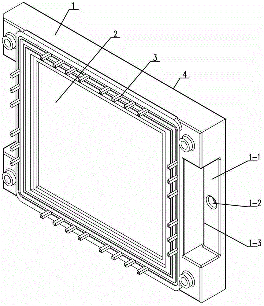
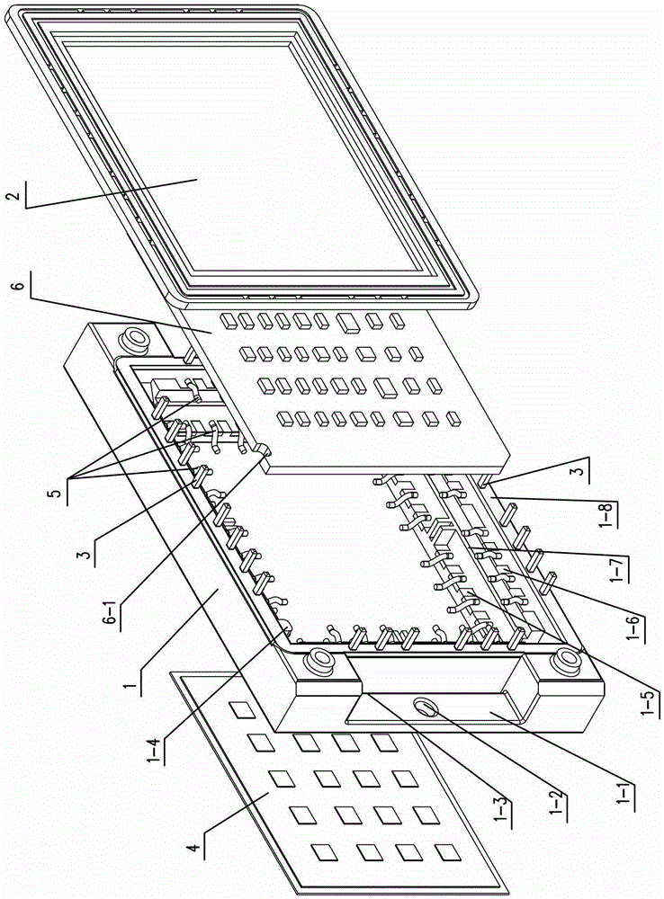
[0016] See Figure 1-3 As shown, the packaging structure of the intelligent power module of the present invention includes a housing 1, a main circuit board 4, a driving circuit board 6 and a plurality of terminals 3, and semiconductor chips, capacitors, resistors, diodes and each terminal 3 are welded on the metal-clad insulation On the metal layer of the substrate to realize circuit connection and form the main circuit board 4 for power conversion, and the driving circuit board 6 is composed of a printed circuit board and resistors, capacitors, diodes, integrated circuits, etc. welded on the printed circuit board, so as to This realizes the input and output of the drive signal. See Figure 4 As shown, each terminal 3 of the present invention is in a stepped shape, and the terminal 3 includes a vertical connecting column 3-1, an upper bonding seat 3-2 arranged at the bottom of the connecting column 3-1, and a lower bonding seat 3-2 at the bottom. 4 and the vertical connecti...


PUM


Abstract

The invention relates to an encapsulation structure of an intelligent power module. Each terminal is in a step shape, and each terminal comprises a vertically arranged connecting pillar, an upper bonding seat arranged on the lower portion of the connecting pillar, a lower bonding seat arranged at the bottom of the connecting pillar, and a vertically arranged connecting seat between the upper bonding seat and the lower bonding seat. A window is arranged on an outer shell, annular step surfaces are arranged on the periphery of the window, and the terminals are embedded in at least two side edges of the window of the outer shell at intervals in a connecting mode. The connecting seats of the terminals are arranged in the outer shell. The lower bonding seats are fixed at a lower step surface of the window, and the upper bonding seats are fixed on an upper step surface of the window. The connecting pillars penetrate through the upper end face of the outer shell. A main circuit board is fixed at the bottom of the outer shell in a sealing mode. The lower bonding seats of the terminals are bonded with the main circuit board through metal bonding wires. The upper bonding seats of the terminals are bonded with driving circuit boards in the outer shell through the metal bonding wires. A cover plate is buckled on the top of the outer shell, and the connecting pillars of the terminals penetrate through the cover plate. The encapsulation structure of the intelligent power module is reasonable in structure, small in size, firm in terminal bonding, convenient to debug, and capable of improving working reliability.

Description

technical field [0001] The invention relates to a packaging structure of an intelligent power module, which belongs to the technical field of power module manufacturing. Background technique [0002] Intelligent power modules (IPM for short) are widely used in AC motor frequency conversion speed regulation and DC motor chopper speed regulation and various high-performance power supplies, such as UPS, induction heating, electric welding machines, active compensation, DC-DC, etc., as well as industrial electrical automation And other fields, has a broad market. The traditional intelligent power semiconductor module mainly includes the casing, the main circuit board and the driving circuit board, semiconductor chips and other devices and multiple terminals welded on the metal-ceramic substrate to form the main circuit board, and the printed circuit board with the integrated circuit chip and various devices welded The drive circuit board constitutes the drive circuit board. In ...

Claims


Application Information

Patent Timeline
Patent Type & Authority Patents(China)
IPC IPC(8): H05K7/14
Inventor 廖学国袁德威纪伟豪周逸凯蔡明原
Owner DELTA ELECTRONICS (SHANGHAI) CO LTD
Features
  • R&D
  • Intellectual Property
  • Life Sciences
  • Materials
  • Tech Scout
  • Unparalleled Data Quality
  • Higher Quality Content
  • 60% Fewer Hallucinations
Learn More