Design method for rebound valve plate thickness of hydraulic oscillating damper

A hydraulic shock absorber and recovery valve technology, which is applied in the field of hydraulic shock absorbers, can solve problems such as difficulty in mastering shock absorbers, lack of shock absorber design technology, and failure to realize modern CAD design of hydraulic shock absorbers.

Inactive Publication Date: 2013-06-12
SHANDONG UNIV OF TECH
View PDF6 Cites 2 Cited by
  • Summary
  • Abstract
  • Description
  • Claims
  • Application Information

AI Technical Summary

Problems solved by technology

At present, there is no accurate and reliable design method for the valve plate thickness design of the cylindrical hydraulic shock absorber in foreign countries. Most of them first determine a valve plate thickness value based on experience, and then finally determine the design parameters through repeated tests, verification and modification methods. The main reason is the lack of reliable shock absorber design technology. For hydraulic shock absorbers, there has not been given an accurate valve deformation analysis formula that can be used for valve plate thickness design. There is a lack of accurate and reliable design methods, and it is difficult to establish an accurate throttle valve. The mathematical model of sheet thickness design, therefore, the hydraulic shock absorber has not yet achieved modern CAD design
In my country, a breakthrough has been made in the parameter design of the throttle valve of the hydraulic shock absorber. For example, Shandong University of Technology has solved the problem of analytical calculation of the deformation of the valve plate, and established an optimal design method for the thickness curve fitting of the shock absorber valve plate, which can obtain reliable The design value of the thickness of the valve plate, the characteristic test value of the shock absorber is close to the required value of the characteristic design, but because this design method needs to establish the optimization objective function of the valve plate thickness, and needs to optimize the design and calculation through programming, for the general shock absorber design difficult to master

Method used


Image

  • Design method for rebound valve plate thickness of hydraulic oscillating damper
  • Design method for rebound valve plate thickness of hydraulic oscillating damper
  • Design method for rebound valve plate thickness of hydraulic oscillating damper

Examples


Embodiment 1

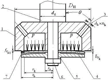
[0049] Embodiment one : The structure of a shock absorber piston assembly and recovery valve is as follows figure 2 As shown, the piston body 1, the piston rod 2, the piston hole 3, the recovery valve plate 4, the limit retaining ring 5, and the fastening nut 6, wherein, in order to prevent the excessive opening of the recovery valve from being too large when the shock absorber moves too fast When the shock absorber breaks down, the limit retaining ring 5 is installed under the recovery valve plate 4, and is fixed with the fastening nut 6; at the same time, in order to increase the service life of the shock absorber, prevent the shock absorber from frequently opening the valve when driving on ordinary roads , The recovery valve is provided with a normally through hole 6. The structural parameters of the shock absorber and the valve body structure and oil parameters are as follows: piston cylinder inner diameter , piston rod diameter d g =20mm, the annular area between t...

Embodiment 2

[0085] Embodiment two : The recovery speed characteristic required by the design of a certain hydraulic shock absorber, such as Figure 6 Shown, the initial valve opening speed , initial valve opening damping force ;Maximum valve opening speed , the maximum valve opening damping force , the structural parameters and oil parameters of the shock absorber are the same as those in Example 1.

[0086] Using the design steps of Embodiment 1, the thickness of the shock absorber recovery valve plate is designed, and the design value of the recovery valve plate thickness obtained h =0.267mm 2 ; The thickness and number of the actual shock absorber recovery superimposed valve slices are:

[0087] ; ; ;

[0088] The equivalent thickness of the actual restored superimposed valve plate is = 0.2674 mm.

[0089] Using the electro-hydraulic servo shock absorber comprehensive performance test bench to carry out the characteristic test on the designed and processed shock ...

Embodiment 3

[0090] Embodiment Three : The recovery speed characteristic curve required for the design of a certain hydraulic shock absorber is the same as that of Embodiment 2; d g =18mm, other structural parameters and oil parameters are exactly the same as those of Example 1.

[0091] Using the design steps of Embodiment 1, the thickness of the shock absorber recovery valve plate is designed, and the design value of the recovery valve plate thickness obtained h =0.243mm 2 ;The thickness and number of the actual restored superimposed valve slices are:

[0092] ; ; ;

[0093] The equivalent thickness of the actual restored superimposed valve plate is = 0.2431 mm.


PUM


Abstract

The invention relates to a design method for rebound valve plate thickness of a hydraulic oscillating damper, which belongs to the technical field of oscillating dampers. The design method is characterized by comprising the following steps: a. determining the optimal design speed point and corresponding oscillating damper damping force of the thickness of a rebound valve plate; b. determining throttling pressure and flow of piston gaps; c. determining flow of a piston hole; d. determining the equivalent length of the piston hole; e. determining the throttling pressure of the piston hole; f. determining the pressure borne by the rebound valve plate at the optimal design speed point; g. determining the pressure borne by the rebound valve plate at the initial valve opening; and h. determining the design thickness h of the rebound valve plate, actual thickness of stacked valve plates hi, and plate number ni. The method can conduct optimal design of the speed point, and accurate design of the rebound valve plate thickness of the oscillating damper according to the oil line of initial valve opening of the rebound valve. Therefore, by utilizing the design method, a reliable design value of the rebound valve plate thickness can be obtained, repeated testing and modification are avoided, design and test expenses are reduced, and the development speed of the oscillating damper is accelerated.

Description

technical field [0001] The invention relates to a hydraulic shock absorber, in particular to a design method for restoring the thickness of a valve plate of a hydraulic shock absorber. Background technique [0002] The damping characteristics of a hydraulic shock absorber are mainly determined by the parameters of the shock absorber recovery valve and compression valve. Among them, the thickness of the valve plate has an important impact on the characteristics of the shock absorber, the damping matching of the suspension system and the ride comfort of the vehicle. At present, there is no accurate and reliable design method for the valve plate thickness design of the cylinder hydraulic shock absorber in foreign countries. Most of them first determine a valve plate thickness value based on experience, and then finally determine the design parameters through repeated tests, verification and modification methods. The main reason is the lack of reliable shock absorber design tech...

Claims


Application Information

Patent Timeline
Patent Type & Authority Applications(China)
IPC IPC(8): F16F9/34
Inventor 周长城孔艳玲提艳
Owner SHANDONG UNIV OF TECH
Why Eureka
Try Eureka